


Металлургические основы термической обработки сталей
Металлургические принципы термической обработки сталей
Термическую обработку сталей проводят для достижения желаемых изменений металлургических структурных свойств сталей. При термической обработке стали претерпевают интенсивные изменения свойств. Обычно очень стабильные стальные структуры получают, когда сталь нагревают до высокотемпературного аустенитного состояния, а затем медленно охлаждают в условиях, близких к равновесным. Этот тип термической обработки, обычно известный как отжиг или нормализация, создает структуру с низким уровнем остаточных напряжений, запертых внутри стали, и структуру можно предсказать по диаграмме равновесия Fe (железо)-C (углерод). Однако свойства, которые в основном требуются от сталей, - это высокая прочность и твердость, которые, как правило, сопровождаются высокими уровнями остаточных напряжений. Это связано с метастабильными структурами, полученными в результате неравновесного охлаждения или закалки из аустенитного состояния.
Кристаллическая структура и фазы
Известно, что кристаллическая структура чистого Fe в твердом состоянии существует в двух аллотропных состояниях. При температуре окружающей среды и до 910°С Fe обладает объемно-центрированной кубической (ОЦК) решеткой и называется альфа-Fe. При 910°С кристаллы альфа-Fe превращаются в кристаллы гамма-Fe с гранецентрированной кубической (ГЦК) решеткой. Гамма-кристаллы сохраняют стабильность до температуры 1400°С. Выше этой температуры они снова приобретают ОЦК-решетку, известную как дельта-кристаллы. Дельта-кристаллы отличаются от альфа-кристаллов только температурной областью своего существования. Fe имеет две постоянные решетки, а именно (i) 0,286 нм для ОЦК-решеток (альфа-Fe, дельта-Fe) и (ii) 0,364 нм для ГЦК-решеток (гамма-Fe). При низких температурах альфа-Fe проявляет сильные ферромагнитные характеристики. Это исчезает при нагревании примерно до 770°С, поскольку решетка теряет ферромагнитное спиновое упорядочение. Состояние Fe выше 770°C называется бета-Fe. Решетка парамагнитных бета-кристаллов идентична решетке альфа-кристаллов.
При переходе из одной формы в другую Fe может переохлаждаться. Это вызывает различие в положении точек превращения при нагреве и охлаждении. Разница зависит от скорости охлаждения и называется гистерезисом. Буквы «с» и «r» указывают, происходит ли превращение за счет нагрева или охлаждения. Кроме того, изменение плотности альфа-Fe по мере его превращения в гамма-Fe приводит к резкому изменению объема материала. Иногда это вызывает напряжения, которые превышают предел упругости и приводят к разрушению. Плотность гамма-Fe примерно на 4 % выше, чем плотность альфа-Fe.
Диаграмма равновесия железа и углерода
Структура сталей, представляющих собой сплавы Fe-C, может содержать либо чистый углерод (графит), либо химическое соединение, известное как цементит (Fe3C), в качестве компонента, обогащенного углеродом. Цементит присутствует даже в относительно медленно охлаждаемых сталях (для разложения Fe3C на Fe и C обычно требуется длительная выдержка при более высоких температурах). По этой причине диаграмму равновесия Fe-C часто рассматривают как диаграмму равновесия Fe-Fe3C. Диаграмма Fe-C стабильна, а диаграмма Fe-Fe3C метастабильна. Диаграмма равновесия Fe-C, включающая как стабильную диаграмму Fe-C, так и метастабильную диаграмму Fe-Fe3C, представлена на рис. 1. Пунктирные линии обозначают стабильную диаграмму Fe-C, а сплошные линии обозначают метастабильную диаграмму Fe-Fe3C.
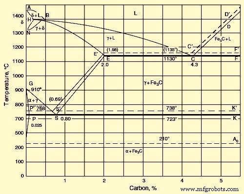
Рис. 1. Диаграмма железа и углерода
На метастабильной диаграмме Fe–Fe3C решетки аллотропных форм Fe (дельта, гамма и альфа) служат местами образования дельта, гамма и твердых растворов С в Fe. Когда стали, обедненные углеродом, кристаллизуются, кристаллы дельта-твердого раствора выпадают в осадок в точках ликвидуса AB и солидуса AH. Дельта-твердый раствор имеет ОЦК-решетку. При максимальной температуре 1490 град С дельта-раствор содержит 0,1 % С (точка Н). При 1490 град С происходит перитектическая реакция между насыщенным дельта-раствором и жидкостью, содержащей 0,5 % С (точка Б). В результате образуется гамма-твердый раствор C в гамма-Fe. Он содержит 0,18% C (точка I).
При содержании С выше 0,5 % гамма-твердый раствор кристаллизуется непосредственно из жидкости (при ликвидусе ВС и солидусе ИЭ). При 1130 град С предельная растворимость С в гамма Fe близка к 2,0 % (точка Е). Снижение температуры от 1130 град С приводит к снижению растворимости С в гамма-Fe на линии ES. При 723°С растворимость С составляет 0,8 % (точка S). Линия ES соответствует осаждению Fe3C из гамма-раствора.
С увеличением содержания С температура перехода гамма-решетки в альфа-решетку снижается, причем переход происходит в температурном интервале, соответствующем кривым GS и GP. Кривая осаждения альфа-фазы GS пересекает кривую осаждения Fe3C ES. Точка S является эвтектоидной с координатами 723 град С и 0,80 % С. В этой точке насыщенный альфа-раствор и осадок Fe3C одновременно образуют гамма-раствор эвтектоидной концентрации. Решетка альфа-твердого раствора идентична решетке дельта-твердого раствора. При эвтектоидной температуре 723 град С альфа-твердый раствор содержит 0,02 % С (точка Р).
Дальнейшее охлаждение приводит к снижению растворимости C в альфа-Fe и при комнатной температуре составляет малые доли процента (точка D). При содержании С 2 % – 4,3 % кристаллизация начинается с выпадения гамма-раствора на линии ВС. Увеличение содержания C выше 4,3 % вызывает выделение Fe3C на линии CD. Выделение избыточной первичной фазы во всех сплавах железа, содержащих более 2,0 % С, сопровождается эвтектической кристаллизацией гамма-раствора и Fe3С в точке С, координаты которой 1130 град С и 4,3 % С. Линия Ао связана с магнитной превращение, которое представляет собой переход из ферромагнитного в парамагнитное состояние.
В случае стабильной диаграммы равновесия Fe-C из-за очень низких скоростей охлаждения С (графит) может кристаллизоваться непосредственно из жидкости. В этом случае вместо эвтектики аустенита и цементита образуется эвтектическая смесь аустенита и графита. Пунктирные линии на рис. 1 символизируют систему Fe-графит. Эти линии находятся при более высоких температурах, чем линии системы Fe-Fe3C. Это свидетельствует о большей устойчивости и близости к полному равновесию системы Fe-графит. Это также подтверждается тем фактом, что нагрев высокоуглеродистых сталей с большим количеством Fe3C приводит к его разложению, описываемому уравнением Fe3C =3Fe + C.
При промежуточных скоростях охлаждения часть стали может кристаллизоваться по системе графита, а часть - по системе цементита. Линии фазового равновесия на диаграммах обеих систем могут смещаться в зависимости от конкретных скоростей охлаждения. Ярко выраженное смещение наблюдается у линий выделения твердого раствора С в гамма-Fe (аустените). По этой причине диаграмма полностью верна только в отношении сталей, подвергающихся относительно медленному охлаждению.
Влияние углерода
Максимальная растворимость С в альфа-Fe наблюдается при 721 град С и равна 0,018 % С. При закалке С может оставаться в альфа-твердом растворе, но вскоре начинается выделение фаз по механизму старения. В твердом растворе C может образовывать либо (i) гомогенный раствор, статически однородное междоузельное распределение, что является редким случаем, либо (ii) неоднородный раствор; с образованием кластеров в местах нарушения структуры кристаллической решетки (границы зерен, дислокации). Последнее является наиболее вероятным состоянием твердого раствора. Образующиеся при этом скопления представляют собой препятствие движению дислокаций при пластической деформации и ответственны за неравномерное развитие деформации в начале пластического течения.
Для анализа влияния содержания C на сплавы Fe-C необходимо учитывать каждый структурный компонент. Медленно охлаждаемые стали содержат феррит и цементит или феррит и графит.
Феррит пластиковый. В отожженном состоянии феррит имеет большое удлинение (около 40 %), мягкий (твердость по Бринеллю 65-130 в зависимости от размера кристалла) и сильно ферромагнитен до 770°С. При 723°С растворяется 0,22% С. в феррите, но при комнатной температуре в растворе остаются только тысячные доли процента С.
Цементит хрупок и имеет более высокую твердость (твердость по Бринеллю около 800). Он слабомагнитен до 210°С и является плохим проводником электричества и тепла. Имеет сложную ромбическую решетку. Обычно различают (i) первичный Fe3C, который кристаллизуется из жидкости на линии CD, (ii) вторичный Fe3C, который осаждается из гамма-раствора на линии ES, и (iii) третичный Fe3C, который осаждается из решение на линии PQ.
Графит мягкий. Он плохой проводник электричества, но хорошо передает тепло. Графит не плавится даже при температурах от 3000°С до 3500°С. Он имеет гексагональную решетку с отношением осей с/а выше 2.
Аустенит мягкий (но тверже феррита) и пластичный. Удлинение аустенита колеблется от 40 % до 50 %. Он имеет более низкую проводимость тепла и электричества, чем феррит, и является парамагнитным. Аустенит имеет ГЦК-решетку.
Структура стали, содержащей 0 % – 0,02 % С, состоит из феррита и третичного Fe3C. Дальнейшее увеличение содержания С приводит к появлению нового структурного компонента – эвтектоида феррита и Fe3C (перлита). Перлит сначала появляется в виде отдельных включений между зернами феррита, а затем при 0,8 % С занимает весь объем. Перлит характеризует двухфазную смесь, которая обычно имеет пластинчатую структуру. При увеличении содержания С в стали до значения выше 0,8 % наряду с перлитом образуется вторичный Fe3C. Вторичный Fe3C имеет форму иголок. Количество Fe3C увеличивается с увеличением содержания C. При 2 % С он занимает 18 % поля зрения микроскопа. Эвтектическая смесь появляется, когда содержание С превышает 2 %. В быстроохлаждаемых сталях не вся избыточная фаза (феррит или Fe3C) успевает выделиться до образования эвтектоида.
Сплавы с 3,6 % С содержат ледебурит (эвтектическая смесь твердого раствора С в γ-Fe и Fe3C). Сплавы более правильно классифицировать с доэвтектическими белыми чугунами.
Критические (трансформационные) температуры
Углерод оказывает заметное влияние на превращения Fe в твердом состоянии. Положение s линий GS и NL на диаграмме равновесия Fe-C показывает, что увеличение содержания C приводит к понижению точки A3 и повышению точки A4 по отношению к их аналогам, показанным на рис. температурный диапазон дельта-фазы.
При образовании эвтектоида (перлита) кривые нагрева и охлаждения имеют остановку. Это обозначено как точка A1 (Ac1 при нагревании и Ar1 при охлаждении). Это явление имеет место при 0,9 % C (точка S на диаграмме Fe–C). Выделение феррита в доэвтектоидных сталях (при пересечении линии ГОС) проявляется на кривых нагрева и охлаждения перегибом, который обозначен точкой А3. Точка соответствует гамма-альфа-превращению в чистом железе. Выделение Fe3C (пересечение линии ES), предшествующее эвтектоидному выпадению, проявляется на кривой охлаждения в виде слабого перегиба, обозначенного точкой Acm (Ac,cm при нагреве и Ar,cm при охлаждении). Добавление C мало влияет на температуру магнитного превращения (точка A2). Следовательно, линия МО соответствует магнитному превращению в сталях с низким содержанием С. В сплавах, содержащих большее количество С, это превращение происходит на линии GOS, что соответствует началу выделения феррита. Если содержание С выше, чем соответствующее точке S, то магнитное превращение совпадает с температурой А1.
Цементит претерпевает магнитное превращение. При любом содержании С превращение происходит при температуре 210°С–220°С. Оно протекает без выраженного гистерезиса, как и магнитное превращение чистого Fe в точке А2.
Структурное превращение в сталях
Когда сталь должна быть закалена, ее нагревают до высокой температуры, чтобы преобразовать общую структуру в аустенитную фазу, которая представляет собой однофазную структуру Fe и C, стабильную при высоких температурах. Если эту нагретую сталь медленно охлаждать, аустенит превращается в перлит, который является равновесной фазой при комнатной температуре. Перлитная структура представляет собой отожженную структуру и является относительно мягкой с низкими физическими свойствами. Если нагретую сталь охлаждать очень быстро, образуется твердая и прочная структура, называемая мартенситом, которая представляет собой метастабильную фазу углерода, растворенного в железе. Эта фаза может быть подвергнута отпуску для получения структуры с более низкой твердостью, которая является менее хрупкой. При промежуточных скоростях охлаждения образуются другие структуры, такие как бейнит, хотя этот тип структуры производится только в больших количествах из легированной стали. В эвтектоидной стали C в основном образуются мартенсит или перлит, в зависимости от скорости охлаждения.
Превращение аустенита в перлит
Превращение ГЦК-решетки аустенита в ОЦК-решетку феррита затруднено из-за присутствия растворенного С в аустените. Решетка аустенита имеет достаточно места для размещения атомов C в центре ячейки. В ОЦК решетке феррита этого пространства нет. Благодаря этому растворимость С значительно снижается при переходе от аустенита к ферриту. Во время бета-альфа-превращения почти весь углерод выпадает из решетки аустенита. В соответствии с метастабильной диаграммой Fe–Fe3C он выпадает в виде цементита. Это преобразование может быть определено тремя взаимосвязанными путями, а именно (i) преобразованием решетки гамма-Fe в решетку альфа-Fe, (ii) осаждением C в виде Fe3C и (iii) коагуляцией карбидов.
При температуре точки А1 превращение по путям (i) и (ii) протекает практически одновременно с образованием пластинчатой смеси феррита и цементита. Атомы растворенного С распределены в решетке случайным образом. Из-за этого Fe3C зарождается в областях, богатых углеродом, а феррит — в областях, где углерода мало, если он вообще отсутствует. Такое перераспределение C происходит путем диффузии и зависит от температуры и времени.
Когда доэвтектоидную сталь, содержащую менее 0,8 % С, подвергают медленному охлаждению, превращение начинается с образования феррита на границе зерен. Эта граница зерна действует как центр кристаллизации феррита. Углерод вытесняется внутрь кристаллита. По мере выделения феррита в центральном объеме достигается концентрация, необходимая для образования феррита. При медленном охлаждении заэвтектоидной стали (С более 0,8 %) при пересечении линии ES Fe3C начинает выделяться на границе зерен. Здесь граница зерна также служит местом кристаллизации.
Скорость диффузии С в решетках γ-Fe и α-Fe быстро уменьшается с понижением температуры, так как коэффициент диффузии зависит от температуры. При соответствующей скорости охлаждения переохлаждение может быть усилено до такой степени, что образование перлита станет невозможным.
В области низких температур механизм превращения и особенности образующейся структуры зависят исключительно от температуры, при которой происходит превращение. С учетом степени переохлаждения различают три диапазона температур превращения, а именно (i) перлитный диапазон, (ii) промежуточный диапазон и (iii) мартенситный диапазон. В этих интервалах температур может происходить непрерывный переход от одного механизма превращения к другому. Процессы превращения сильно зависят от содержания С и других элементов в стали. Они могут начинаться по более быстрому механизму и заканчиваться по более медленному.
В перлитной области превращение характеризуется одновременным образованием смеси феррита и карбида. На границе аустенитного зерна может выделяться свободный феррит или карбид. При этом образование и рост обеих фаз контролируются диффузионными процессами. Значительную роль играет диффузия Fe и других элементов. Тонкость структуры увеличивается с понижением температуры, пока не потребуется больше времени для диффузионной кристаллизации феррита и карбидов.
Перлит представляет собой механическую смесь ферритных и карбидных пластин, образующуюся при превращении в перлитной области. Скорость образования зародышей кристаллизации перлита зависит от пересыщения аустенита карбидом, которое увеличивается с понижением температуры. Скорость также зависит от скорости диффузии, которая уменьшается с температурой. Рост островков перлита зависит главным образом от скорости диффузии атомов C и Fe. Другими факторами являются (i) степень перенасыщения и (ii) преимущество свободной энергии во время образования феррита. Перлитные островки растут не только за счет образования новых плит, но и путем дальнейшего роста старых плит во всех направлениях. Твердосплавные пластины растут быстрее, чем ферритовые.
Процесс образования перлита начинается с образования зародышей феррита. Многократное чередование зарождения пластин феррита и цементита и разветвления пластин обеих фаз приводит к формированию плоскопараллельных и веерообразных перлитных пластин. Зародыши перлита появляются преимущественно в областях решетки с дефектами кристаллической структуры, такими как границы зерен, нерастворимые карбиды или неметаллические включения. Очень важной особенностью перлита является расстояние между пластинами. Прочностные свойства стали улучшаются с уменьшением межосевого расстояния.
Скорость образования центров кристаллизации Fe3C и феррита в перлитной области увеличивается с понижением температуры. Расстояние между пластинами уменьшается по мере увеличения тонкости структуры.
Важным признаком, влияющим на свойства стали, является размер колонии перлита. Уменьшение размера колонии сопровождается ростом ударной вязкости и снижением хрупкости. Критическая температура хрупкости зависит от морфологии перлита. Так, при разрушении ферритовых и цементитных пластин образуется относительно высокопрочный перлит, образующий высокую плотность дислокаций внутри феррита.
Повышение прочности перлита на излом достигается за счет сфероидизации частиц Fe3C. Сфероидизации может способствовать деформация перлита, последующий нагрев и выдержка при температуре, близкой к Ac1. Другой способ, обеспечивающий относительно высокую прочность и пластичность перлита, заключается в деформации при перлитном превращении. Это приводит к образованию полигональной структуры и сфероидизации цементита. Предел текучести (YS) смеси феррит-перлит зависит от свойств феррита и перлита аддитивным образом.
Превращение аустенита
При превращении аустенита в доэвтектоидных и заэвтектоидных сталях перлитному превращению предшествует выделение избыточных фаз – феррита и вторичного цементита. Относительное количество структурно свободной избыточной фазы зависит от степени переохлаждения аустенита. Количество избыточного феррита или Fe3C уменьшается с увеличением скорости охлаждения. При достаточной степени переохлаждения можно избежать образования избыточной фазы как самостоятельного структурного компонента.
При медленном охлаждении доэвтектоидной стали, содержащей небольшое количество эвтектоидного аустенита, на зернах избыточного феррита растет эвтектоидный феррит, а эвтектоид Fe3C остается в виде структурно свободных прослоек на границе зерен. В заэвтектоидной стали эвтектоид также может подвергаться структурной дегенерации. Цементит, образующийся в результате эвтектоидного осаждения при очень низком охлаждении ниже точки А1 (выше 700 град С), откладывается на вторичном цементите. Рядом отмечаются участки структурно свободного феррита. Это эвтектоидное превращение, сопровождающееся расслоением фаз, считается аномальным. При нормальном эвтектоидном превращении феррит и Fe3C срастаются в виде колоний с закономерным чередованием двух фаз. В случае необычного превращения грубая смесь феррита и Fe3C не имеет отчетливой эвтектоидной структуры. При эвтектоидном превращении механизм может измениться с аномального на нормальный. Следовательно, при быстром охлаждении и соответственно выраженном переохлаждении аустенита аномальное превращение можно вообще подавить.
В случае избыточного феррита в доэвтектоидных сталях феррит встречается в двух формах, а именно (i) компактные равноосные зерна и (ii) ориентированные пластины Видманштетта. Компактные выделения доэвтектоидного феррита появляются в основном на границе аустенитных зерен, тогда как видманштеттовы пластины формируются внутри зерен. Феррит Видманштетта наблюдается только в сталях с содержанием углерода менее 0,4 % и достаточно крупными зернами аустенита. По мере уменьшения размеров аустенитных зерен увеличивается доля феррита в виде равноосных зерен. Видманштеттов феррит формируется в температурном интервале от А3 (50 град С) до 600 град С до 550 град С. С увеличением содержания С в стали доля видманштеттова феррита в структуре снижается.
Предполагается, что видманштеттеновый феррит образуется за счет сдвиговой гамма-альфа-перестройки решетки, сопровождающейся упорядоченным взаимосвязанным движением атомов. Равноосные зерна феррита растут путем нормальной диффузионной перестройки решетки с неупорядоченным переходом атомов через границу гамма/альфа.
Один из способов упрочнения сталей заключается в обеспечении структуры доэвтектоидным ферритом, содержащим дисперсные карбидные выделения. Для получения такой структуры сталь необходимо нагревать до растворения специальных карбидов в аустените, а затем быстро охлаждать, чтобы предотвратить обычное выделение карбида непосредственно из аустенита до начала образования доэвтектоидного феррита.
Превращение мартенсита
Превращение мартенсита происходит за счет закалки (быстрого охлаждения) высокотемпературной фазы. Основные характеристики мартенситного превращения в углеродистых сталях приведены ниже.
- Мартенситное превращение происходит за счет быстрого охлаждения стали от температуры выше А1, скажем, в воде. Благодаря быстрому охлаждению подавляется диффузионное выделение аустенита в двухфазную смесь феррита и карбида. Концентрация С в мартенсите соответствует таковой в аустените. Мартенситное превращение происходит без какой-либо диффузии.
- Превращение аустенита в мартенсит начинается с начальной температуры мартенсита (Ms). Ms обычно не зависит от скорости охлаждения. Мартенсит образуется в определенном интервале температур. Конкретная температура определяется содержанием углерода в стали.
- Прекращение охлаждения в температурном интервале Ms-Mf (мартенситная отделка) приостанавливает образование мартенсита. Эта особенность отличает мартенситное превращение от перлитного. При перлитном превращении превращение продолжается до конца при постоянной температуре ниже точки А1, и конечным результатом является полное исчезновение аустенита при достаточном времени изотермической выдержки. При мартенситном превращении остается некоторое количество остаточного аустенита.
- Мартенситное превращение не имеет инкубационного периода. Некоторое количество мартенсита мгновенно образуется ниже температуры Ms.
- При охлаждении ниже Ms количество мартенсита быстро увеличивается из-за быстрого образования новых пластин. Первоначально сформированные пластины со временем не растут.
- Решетка мартенсита правильно ориентирована относительно решетки аустенита. Между решетками существует определенная ориентация.
Температура Ms характеризует сталь определенного состава, подвергнутую определенной предварительной обработке. В данной стали мартенситное превращение начинается при одной и той же температуре независимо от скорости охлаждения. Эта температура зависит от состава стали и сильно снижается по мере увеличения содержания углерода в стали. Часть С переходит в карбиды, которые сосуществуют с аустенитом. Карбиды растворяются в аустените при повышении температуры закалки. Следовательно, концентрация C в аустените увеличивается, а точка Ms снижается.
Образование мартенсита рассматривается как сдвиговый механизм перестройки решетки аустенита. Хорошо известен мартенситный (сдвиговый) механизм фазового превращения за счет упорядоченного взаимосвязанного движения атомов на расстояния, меньшие межатомного расстояния, при этом атомы не меняются местами. Атом в начальной фазе сохраняет своих соседей в мартенситной фазе. Это основная особенность сдвиговой перестройки решетки.
Такой характер перестройки решетки обеспечивает согласованность границы между старой и новой фазами. Когерентность (упругое сопряжение) решеток на границе мартенсита и исходной фазы обеспечивает очень быстрое движение границы к матрице даже при низких температурах. Атомы совместно перемещаются на расстояния, меньшие межатомного расстояния, что приводит к росту мартенситного кристалла.
При росте мартенситного кристалла на границе когерентности накапливается упругая деформация. При достижении YS когерентность нарушается. Атомы разупорядочены на границе мартенситного кристалла и исходной матрицы. Скользящее движение границы становится невозможным. Следовательно, рост кристалла по мартенситному механизму прекращается, и в дальнейшем кристалл может расти только за счет диффузии. Но мартенситное превращение происходит при низких температурах, когда скорость диффузии очень мала. Следовательно, после нарушения когерентности рост мартенситного кристалла практически не наблюдается.
Полиморфное превращение твердых растворов по мартенситному механизму характеризуется отсутствием диффузионного перераспределения компонентов. Здесь описаны условия, необходимые для мартенситного механизма перехода высокотемпературной фазы в низкотемпературную. Мартенситное превращение невозможно при малом переохлаждении. Это связано с тем, что при неупорядоченной перестройке решетки упругая деформация определяется только изменением объема, тогда как при мартенситном превращении дополнительно зависит от когерентности решеток исходного и мартенситного кристаллов. С увеличением степени переохлаждения скорость неупорядоченной перестройки решетки увеличивается, достигает максимума, а затем падает. Для получения мартенситного механизма полиморфного превращения в Fe сталь необходимо сильно перегреть в гамма-диапазоне, а затем очень быстро охладить, чтобы подавить развитие нормального превращения.
При образовании мартенсита происходит перестройка ГЦК-решетки аустенита в ОЦК-тетрагональную решетку мартенсита, аналогичную ОЦК-решетке альфа-Fe. Решетка аустенита превращается в мартенситную посредством деформации Бейна, заключающейся в сжатии тетрагональной ячейки аустенита по оси с и одновременном увеличении размеров по оси а. Степень тетрагонального искажения решетки мартенсита, с/а, растет прямо пропорционально концентрации С мартенсита. Мартенситная решетка сохраняет тетрагональность при комнатной температуре. Установлена ориентационная связь исходной и мартенситной фаз.
Существует множество гипотез о природе зарождения мартенсита. Многие из них выступают за гетерогенное зародышеобразование на особых участках дефектов в исходной матрице.
По морфологии мартенсит делится на два основных типа. Это пластинчатый мартенсит и массивный мартенсит. Они различны по форме, взаимному расположению кристаллов, субструктуре и плоскости габитуса. Пластинчатый (игольчатый) мартенсит чаще встречается в высокоуглеродистой стали. Кристаллы мартенсита имеют форму тонких линзовидных пластин. Пластины, которые появляются первыми, проходят по всему агрегату, делят его на отдельные части. Но они не могут пересекать границу зерен матрицы. Следовательно, размер пластины ограничен размером аустенитного зерна. В аустенитных участках образуются новые мартенситные пластины. Здесь размер пластины ограничен размером сечения. При малом аустенитном зерне мартенситные пластины настолько мелки, что игольчатая структура мартенсита не видна на образцах шлифа. Такой мартенсит называется бесструктурным мартенситом, и он наиболее желателен.
Массивный (реечный) мартенсит можно наблюдать в низкоуглеродистой и среднеуглеродистой стали. Кристаллы этого типа мартенсита имеют форму соединенных между собой пластин, имеющих примерно одинаковую ориентацию. Пластины массивного мартенсита разделены малоугловыми границами.
Превращение бейнита
Превращение бейнита является промежуточным между перлитным и мартенситным превращениями. Кинетика превращения бейнита и образующаяся структура имеют черты как диффузионного перлитного превращения, так и бездиффузионного мартенситного превращения. В результате этого превращения образуется смесь феррита и карбида. Эта смесь называется бейнит. Механизм превращения бейнита включает гамма-альфа-перестройку решетки, перераспределение C и осаждение карбида.
Здесь объясняется близость бейнитного превращения к его перлитному и мартенситному аналогам. Диффузионное движение атомов основного компонента Fe практически полностью подавлено в области бейнитного превращения. Тогда образование феррита из гамма-альфа затруднено из-за подавления выделения перлита. Однако диффузия С довольно активна и вызывает выделение карбидов. В промежуточном диапазоне кристаллы гамма-фазы формируются путем когерентного роста, как мартенситные пластины. Но пластины альфа-фазы формируются медленно, а не мгновенно.
This is due to the fact that over the intermediate temperature range the alpha phase can precipitate only from the C depleted gamma phase. Thus the growth rate of the alpha phase crystals depends on the C diffusive removal rate. In this case, the martensite start point Ms in austenite rises and the martensite gamma to alpha transformation takes place at temperatures above the temperature Ms typical of the steel with a given composition.
At the instant of martensite transformation, the C concentration remains unchanged. Only the crystal lattice is altered and a supersaturated a solution is formed. Carbide precipitates after gamma to alpha transformation.
There is a difference between upper and lower bainite, which are formed in the upper and lower parts of the intermediate temperature range. The conventional boundary between the bainite is close to 350 deg C. Upper bainite has a feathery structure, whereas lower bainite shows an acicular morphology, which is close to that of martensite. The difference in the structures of upper and lower bainite is due to the difference in the mobility of C in the upper and lower parts of the bainite temperature range.
The alpha phase substructure of upper bainite resembles the substructure of massive martensite in low C steel, while the alpha phase structure of lower bainite approaches the structure of martensite in high C steels. In upper bainite, carbide particles can precipitate both at lath boundaries and inside laths. This fact suggests that here carbides precipitate directly from austenite. In lower bainite, carbide is found inside the alpha phase. This is since carbide is formed during precipitation of a supersaturated solid solution of C in the alpha phase. Both upper and lower bainite shows a high density of dislocations inside the alpha phase. Fe3C is the carbide phase in upper bainite and epsilon carbide (Fe2C) in lower bainite. As the holding time is increased, Fe2C turns into cementite. The dimensions of austenite grain have no effect on the kinetics of martensite transformation.
Tempering
The processes which take place during tempering are precipitation and recrystallization of martensite. Quenched steel has a metastable structure. If subjected to heating, the structure becomes closer to equilibrium. The nature of the processes which occur during tempering is determined by three major characteristics of quenched steel namely (i) strong super saturation of the martensite solid solution, (ii) high density of crystal lattice defects (dislocations, low angle and large angle boundaries, and twin interlayers etc.), and (iii) presence of retained austenite.
The main process taking place during tempering of steel is the precipitation of martensite accompanied by formation of carbides. Depending on the temperature and duration of tempering, the martensite precipitation can involve three stages namely (i) pre-precipitation, (ii) precipitation of intermediate metastable carbides, and (iii) precipitation and coagulation of cementite. Retained austenite can precipitate simultaneously. Since there is a high density of dislocations in martensite, hence its substructure is similar to the substructure of steel which is work hardened. Hence, polygonization and recrystallization can develop during tempering.
When C steel is tempered, super-saturation of the gamma solution in austenite increases with an increase in the C content of steel. This leads to lowering of the Ms-temperature and transition from massive martensite to plate martensite. The amount of retained austenite also increases.
The segregation of C represents the first structural changes which take place during tempering of C steel. The segregated C can nucleate heterogeneously at lattice defects or homogeneously in the matrix. The heterogeneous nucleation of the segregated C takes place either during quenching or immediately after it.
Flat homogeneous clusters of C atoms not connected with lattice defects are formed at tempering temperatures of less than 100 deg C. This is due to the considerable displacements of Fe atoms and the appearance of elastic distortions. As the tempering temperature is increased, the clusters become larger and their composition is close to Fe4C. This process is dependent on the C diffusion. Metastable Fe2C is formed above 100 deg C. It has a hexagonal lattice and appears directly from C clusters when the C concentration is increased. Metastable Fe2C can also precipitate directly from the alpha solution. Fe2C precipitates as very fine (10 nm to 100 nm) plates or rods at low temperatures. With an increase in tempering temperature or time, Fe2C particles become coarser and precipitate in steels containing a minimum of 0.2 % C. In steels with a high Ms-temperature, partial precipitation of martensite is associated by the deposition of excess carbide and is obtained during quench cooling in the martensite range. Hence self-tempering of these steels occurs during their quenching.
Cementite is formed at a temperature higher than 250 deg C. Two known mechanisms of Fe3C nucleation are (i) precipitation directly from a supersaturated alpha solid solution and growth of Fe3C particles at the expense of the dissolution of less stable carbides, and (ii) appearance of Fe3C as a result of transformation of the intermediate carbide lattice to the Fe3C lattice.
In the final stage of the carbide formation during tempering, coagulation and spheroidization of carbide take place. These happen intensively starting from 350 deg C to 400 deg C. At temperatures higher than 600 deg C, all Fe3C particles have a spherical shape and undergo coagulation only.
A substantial part of the tempering process is devoted to the precipitation of retained austenite accompanied by deposition of carbides. Precipitation occurs over the temperature range of 200 deg C to 300 deg C. During tempering, retained austenite transforms into lower bainite.
A decrease in the C concentration of the alpha phase during carbide formation results into changes in the phase structure. Martensite precipitation is conventionally divided into two stages. The first stage of precipitation is achieved below 150 deg C when the mobility of C atoms is sufficient for the formation of carbide plates. But, it is insufficient for the carbide plates to grow by diffusion of C from the areas of non-precipitated martensite with a high C concentration. This results in a non-uniform content of C in different areas of the martensite and hence inhomogeneity of martensite results with respect to its tetragonality. In areas with precipitated carbide, tetragonality is lower than in non-precipitated areas. Two solid solutions with different C concentrations coexist. For this reason the precipitation is referred to as a two -phase precipitation. The two phase precipitation of martensite results from the deposition of new carbide particles in areas containing martensite with the initial C concentration. Carbide particles do not grow at this stage.
At the second stage of martensite precipitation (150 deg C to300 deg C the alpha solution is depleted of C owing to diffusive growth of carbide particles, but the process proceeds very slowly. Hence, the precipitation kinetics is due to the rapid depletion of the alpha solution in carbon. Subsequently, depletion of the solid solution in C stops. At 300 deg C around 0.1 % C is left in the alpha solution. Above this temperature, no difference between the lattice of the alpha solution and that of the alpha-Fe is detected. Below 300 deg C the degree of tetragonality is still measurable. Above 400 deg C the alpha solution becomes completely free of excess C and transformation of martensite to ferrite is finished.
Plates (needles) of quench martensite have a high density of dislocations which is comparable to the density of the deformed steel. However, recrystallization centres and their progress to recrystallized grains are not observed. This is since carbide particles pin dislocations and large angle boundaries. It is only above 600 deg C, when the density of the particles decreases owing to the coagulation, that the recrystallization growth of grains takes place at the expense of migration of large angle boundaries. With this the morphological structures of lath martensite disappear. These processes are hampered in high C steels as compared to low C steels, since the density of carbides is greater in high C steels. The acicular structure is retained up to the tempering temperature of around 650 deg C.
The structural changes which occur during tempering cause alteration of steel properties. These changes depend on the tempering temperature and time. Hardness decreases as the tempering temperature is increased.
Kinetics of transformation of austenite
The kinetics of transformation of austenite is described below.
Isothermal transformation diagrams
It is important to follow the process at a constant temperature for the understanding of the kinetics of the transformation to austenite. For this purpose, isothermal transformation (IT) diagram is usually made which illustrates the isothermal process of austenite precipitation. In IT diagram (Fig 2), the transformation time is in the X-axis shown on the logarithmic scale and the temperature is plotted on the Y-axis. From this diagram, the incubation period (left hand curve) can be determined and also the time required for completion of the process (right hand curve). The instant, steel passes the points A3 and A1 during quenching, is usually taken as the zero time reference.
The time required to achieve the temperature of the quenching medium is frequently neglected. The start and finish of the transformation are difficult to determine from the transformation curve behaviour at the initial and final sections of the curve. Hence, the lines of the IT diagram generally correspond to a certain final volume which has undergone transformation, e.g., 2 % and 98 % for the transformation start and finish, respectively. The volume value is usually not shown in the IT diagram.
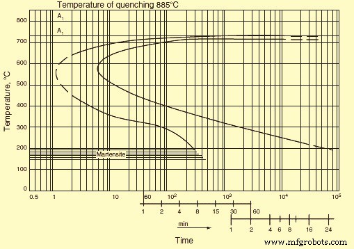
Fig 2 Isothermal transformation diagram
In addition to the curves stated above, IT diagram frequently contains intermediate curves corresponding to certain values of the transformed volume, say 20 %, 50 %, or 80 %. A decrease in the transformation rate causes displacement of the transformation start and finish curves to the right, i.e., toward greater duration. This phenomenon can be seen if the quenching heating temperature increases as a result of a decrease in the number of inclusions and growth of austenite grains. An increase in the transformation rate leads to displacement of the curves to the left. This phenomenon can be accounted for (i) by a decrease in the quenching heating temperature, (ii) the presence of carbides or inclusions, and (iii) refinement of the austenite grain. For a specified sample of steel the temperature which corresponds to a maxi mum transformation rate (the nose of the sigmoid curve) does not, as a rule, change significantly.
Continuous cooling transformation diagrams
Continuous cooling transformation (CCT) diagrams consider the transformation kinetics of eutectoid steel. The major transformation which takes place during annealing cooling of steel is a eutectoid precipitation of austenite into a mixture of ferrite and carbide. The eutectoid transformation kinetics is given by IT diagrams of austenite at a temperature of 727 deg C. The structure attained after tempering below 300 deg C is called tempered martensite. An acicular structure is seen after tempering at 300 deg C to 450 deg C. Tempering over the temperature interval of 450 deg C to 600 deg C shows a distinct dot structure. Austenite is in a thermodynamically stable equilibrium with the ferrite-Fe3C mixture. Stability of undercooled austenite is defined by a period of time during which the appearance of precipitation products in the diagram cannot be registered by conventional methods. The degree of austenite undercooling is the main factor which determines the steel microstructure. The necessary degree of undercooling is provided by either continuous cooling or isothermal treatment.
As seen earlier, in hypo-eutectoid steels the formation of pearlite is preceded by precipitation of hypo-eutectoid ferrite. With a decrease in the transformation temperature and an increase in the degree of undercooling, precipitation of hypo-eutectoid ferrite is suppressed. The amount of pearlite increases and the C content becomes less than that in pearlite of the eutectoid steel. In the region of the maximum transformation rate, the two curves merge. Thus, a purely pearlitic structure is formed in steel with 0.4 % C. In steels containing higher amounts of C, the precipitation of ferrite cannot be suppressed even if the C content decreases. Ferrite precipitation precedes the formation of pearlite even at a maximum transformation rate, but the amount of ferrite is less than that is formed at smaller undercooling.
These propositions are valid for the precipitation of cementite in hyper-eutectoid steels, but it can be suppressed even at relatively small undercooling. In this case, the C content of pearlite becomes higher than that in the eutectoid steel. As a result of suppression of the hypo-eutectoid ferrite precipitation under continuous cooling from the region of the gamma solid solution, the point Ar3 lowers much faster than the point Ar1 as the cooling rate is increased. With a certain cooling rate, both points merge into one point, which corresponds to the formation of a fine plate structure of the pearlite type free of ferrite.
Under continuous cooling the transformation process can also be visualized as diagram in temperature-time coordinates. Therefore the behaviour of cooling curves is to be analyzed to find characteristics of the transformation processes. In this diagram, the ferrite and pearlite start lines are shifted toward longer periods of time compared to the IT diagram. This is due to an increase in the temperature interval necessary for preparing the transformation processes in the austenite lattice. As a result, only part of the incubation period, which is needed for the IT to start, is effective. In this case, the incubation period is the mean of the effective lengths of time corresponding to different periods of time in the given range. This proposition can be used to calculate the behaviour of the transformation start line in the pearlite range from the IT diagram. The reverse calculation is also possible.
Similar to the pearlite range, in the bainite temperature range, the precipitation of undercooled austenite starts after a certain incubation period. Resemblance of the bainite and pearlite transformation kinetics consists not only in the presence of an incubation period but also in the character of the volume increase during isothermal soaking which is the fraction of the transformed volume of austenite increases first with acceleration and then with deceleration. At the same time, as in the case of the martensite transformation, retained austenite does not disappear completely during the bainite transformation. Every point in the bainite finish curve corresponds to certain amount of retained austenite. Similar to the pearlite transformation, the bainite transformation can take place both during isothermal soaking and under continuous cooling. Austenite which has not been transformed over the bainite range turns partially into martensite when the steel is cooled to room temperature. Since the austenite is inhomogeneous with respect to the C content after the bainite transformation, martensite is formed predominantly in C enriched regions.
For the high alloy steel, IT curves can be separated by a temperature interval in which undercooled austenite is highly stable. In this interval, pearlite precipitation does not take place for many hours, while undercooling is inadequate for the bainite transformation. In C steel, the bainite transformation proceeds concurrently with the pearlite transformation. Products of the pearlite transformation dominate at higher temperatures, and those of the bainite transformation at lower temperatures.
During the transformations of austenite on cooling in the martensite range, martensite component in the steel structure appears when the cooling rate achieves a certain value. The minimum cooling rate at which the martensite component is formed is called the lower critical rate of cooling. The rate at which transformations by the pearlite and bainite mechanisms are suppressed completely is referred to as the upper critical rate of cooling (quenching). If the conditions of austenite formation (austenitization temperature and the holding time at this temperature) and the cooling conditions (cooling rate exceeds the upper critical rate) are constant, the location of the martensite start point Ms depends only on the contents of C and alloying elements in the steel.
If the cooling rate is high, the formation rate of separate needles of martensite is also high, and transformation of austenite to martensite begins on reaching Ms-temperature. It continues on subsequent cooling to lower temperatures. As the temperature of the quenching medium is lowered, the amount of formed martensite increases first quickly and then slowly. With an increase in the quenching heating temperature (austenitization temperature), the transformation also shifts toward lower temperatures as more of the alloying elements are taken into solution. A certain amount of martensite can be formed during isothermal holding, but it is not high in C steels. Retained austenite is stabilized during isothermal holding. As a result, more martensite is formed during subsequent cooling. Formation of martensite stops at the point Mf. There is a relationship between some factors which influence the stabilization of martensite. The effect of stabilization increases with the amount of martensite in the structure or, the amount of martensite being equal, with temperature.
There is a close link between the CCT and IT diagrams. When resolving practical issues involved in heat treatment of steel, it is sometimes necessary to know how the continuous cooling rate affects the structure formed as a result of austenite transformation. For this, there have been efforts to establish the relationship between the transformation kinetics of austenite under isothermal conditions and under continuous cooling conditions. The efforts have started from the concept of additivity of the transformation processes at different temperatures. It has been presumed that holding of undercooled austenite at a preset temperature is part of the incubation period. However, it has been found, that calculated and experimental data coincide satisfactorily only if the pearlite transformation is continuous.
If the pearlite transformation is preceded by precipitation of eutectoid pearlite or the pearlite and bainite transformations occur concurrently, calculated data are at a discrepancy with the experimental data. It has been found that the discrepancy is due to the factors namely (i) holding of austenite during the time accounting for fractions of the incubation period causes acceleration of the subsequent intermediate transformation at the expense of preparatory processes, (ii) precipitation of hypo-eutectoid ferrite alters the austenite composition which delays the subsequent intermediate transformation, (iii) partial transformation of austenite over the intermediate range reduces the rate of the said trans formation at lower temperatures and facilitates an increase in retained austenite which is due to a redistribution of C and enrichment of the non-transformed part of austenite in carbon, and (iv) a change in the cooling rate over the martensite range affects stabilization of austenite in different ways.
For the above reason, special methods of constructing thermo-kinetic transformation diagrams of austenite subject to continuous cooling have been elaborated for non-eutectoid steels. From these diagrams it is possible to determine the critical rate of quenching cooling or continuous cooling which is necessary to complete a particular stage of austenite precipitation.
It has been seen that the CCT diagram is a function of the bar diameter. When steel is subjected to martensitic hardening, it is required to be cooled from the quenching temperature so that on undercooling to a temperature below the Ms point austenite has no time to precipitate and form a ferrite-carbide mixture. For achieving this, the cooling rate is to be less than the critical value. The critical cooling rate is the minimum rate at which austenite does not precipitate to a ferrite-carbide mixture. Of course, the cooling rate of steel products is non-uniform over their cross section. It can be higher than the critical rate on the surface and lower than the critical rate at the centre.
The critical cooling rate at different points of a product can be directly determined from an IT diagram. In the first approximation, it is given by the slope of the tangent to the C curve which denotes the austenite precipitation onset. This method gives a value which is around 1.5 times the true critical rate. The cooling rate can be determined more accurately if thermo-kinetic diagrams are used. Intercepts of the cooling curves with the lines of the thermo-kinetic diagrams show the start and finish temperatures of the corresponding transformation.
From the transformation diagram, it is possible to determine, for example, the rate which provides 40 % martensite in the structure or the rates at which the entire transformation occurs in the pearlite range, i.e., hardening is omitted altogether. Because the data on the critical hardening rate depend on cooling time and is to be associated with a specific temperature (at which direct measurements of the hardening rate are practically impossible), it is proper to specify the cooling time for a specific interval of temperature, for example, from the point A3 to 500 deg C. Point A3 in the diagram is the time reference. Then it is possible to directly determine the critical cooling time K (Km for fully martensitic hardening, Kf for initial appearance of ferrite, and Kp for full transformation in the pearlite range).
Since the cooling time and the progress of the subsequent cooling of the sample during end-face hardening are known, the outcome of hardening can be determined from the transformation diagram. It is to be remembered that a transformation diagram is valid only for particular conditions of melting and homogenization. Deviations in the composition or grain dimensions cause changes in the trend of thermodynamic curves. This is explained by the fact that an increase in the homogenization temperature and time and, consequently, enlargement of the grains enhance the stability of austenite. Conversely, refinement of grains lowers the critical cooling rate, since stability of austenite decreases with an increase in the extent of grain boundaries.
Hardenability
The depth of the hardened zone is termed hardenability. This is one of the most important characteristics of steel. Since the cooling rate is non-uniform along the cross section of a sample, austenite can pass into martensite in surface layers only, while at the centre of the sample austenite undergoes the pearlite transformation. In the first place, hardenability depends on the critical cooling rate. An examination of the temperature curves plotted for different areas of the sample shows that the cooling rate of the core of a large diameter product is lower than the critical value and hence the core is not martensitically hardened. Martensite is present in the surface layer only.
After hardening treatment, a bulky part with a large cross section can show the entire range of structures such as a smooth transition from martensite near the surface through troostite-martensite and troostite to pearlite at the centre. The geometry of samples can influence the character of the cooling curves. However, given the same surface-to-volume ratio, the curves coincide in general. The highest changes in the cooling rate are experienced by the diameter of samples.
Considering the above, for achieving a through hardening of bulky products or full martensitic hardening to the core of a product, it is essential to provide the critical hardening rate along the entire cross section of the product. IT and CCT diagrams can be used to determine this rate. The diagrams are usually plotted for different grades of steel, taking into account the progress of cooling in different sections and in different hardening media.
The hardenability of steels depends on the steel composition, specifically on the C content. In the steel hardenability diagrams, the hardenability of each grade of steel is normally presented as a hardenability band. These diagrams have been plotted for almost all existing grades of steel. They show how to achieve hardening of a product made of particular steel.
Hardenability of steel is also categorized by IT curves. The more the curve is shifted to the right along the X-axis, the greater is the hardenability of the steel. This is explained by the fact that the rightward shift of the IT curve is due to better stability of austenite.
An improvement in the stability of undercooled austenite and hence an increase in the critical hardening rate lead to a greater depth of hardening. Then hardenability depends on all the factors which improve the stability of undercooled austenite. As an example, the stability of austenite can be raised by alloying steel with chromium and tungsten. These elements lower the austenite precipitation rate and can make steel an air-hardening one. Steel with a normal content of impurities is hardened to strength ten times that of a pure Fe-C alloy.
Elevation of the hardening temperature favours an increase in the hardening depth due to the homogenization of austenite and enlargement of austenite grains. Refinement of grains impairs hardenability as grain boundaries affect the stability of austenite. The hardening depth also depends on the hardening medium used. The greater is the intensity of cooling, the greater is the depth of hardening. Besides, the hardening depth depends on the cross-sectional diameter of the products. The critical diameter is that of the greatest cross section which lends itself to through hardening in a given hardening medium. The critical diameter is different for different hardening media and characterizes the hardenability provided by a particular method only.
Hardenability has an effect on the mechanical properties of steel. In the case of through hardening, the properties do not differ along the cross section of a product. Otherwise they decrease from the surface to the centre. The analysis of the influence of hardenability on the properties of steels which have been tempered after hardening shows that a high temperature favours equalization of hardness along the cross section. However, the structure of weakly hardenable steels remains inhomogeneous. This is due to a grain structure appearing on the surface, where martensite is formed during quenching, while a lamellar structure remains at the centre. A grain structure is present along the entire cross section of through-hardening steel. This determines the character of changes in the properties of steels with different hardenability. The properties which are independent of the Fe3C form (YS, specific elongation, impact strength) differ.
The properties of tempered steels (fracture stress, YS, impact strength, reduction in area) are impaired if ferrite precipitates during quenching. The mechanical properties of a product depend on its cross-sectional area. To obtain the best mechanical properties in the tempered state, a grain structure is required to be provided along the entire cross section; i.e., through hardenability is to be ensured in the quenched state.
Grain size
It is necessary to know the material structure while analyzing any processes or properties associated with grain boundaries. Most of the steel materials have polycrystalline structure and they comprise a set of grains separated by boundaries. The grain boundary is one of the basic structural elements in polycrystalline steel materials. The grain boundary represents an interface between two differently oriented crystals. This is the region of crystal imperfection. It is capable of moving and adsorbing impurities. The boundary has a high diffusive permeability.
In polycrystalline steel materials, the boundaries determine the kinetics of many processes. For example, movement of grain boundaries controls the process of recrystallization. A high diffusive permeability of grain boundaries determines the kinetics of diffusion-dependent processes at moderate temperatures. Embrittlement of steel material is connected with enrichment of grain boundaries in impurities.
Grain boundaries are normally divided into two large groups namely (i) low angle boundaries, and (ii) large angle boundaries. Low angle boundaries are sub-grain boundaries with an angle of less than 10 degrees. They represent networks or walls of dislocations. The structure of large angle boundaries is much more complicated. The progress in understanding the structure of grain boundaries is connected with elaboration of the models describing the observed microscopic properties of the boundaries.
Grain size determination
The size of the grain that is formed under a given treatment is determined from micro-sections after their etching. For C and alloyed steels the reagent used is 1ml to 5 ml HNO3 +100 ml ethyl or methyl alcohol. Austenitic steel is etched in a copper sulphate-chloride solution containing 10 grams copper sulphate, 50 ml hydrochloric acid, and 50 ml water. When C and low alloy steels are etched, the reagents turn pearlite dark and make visible the ferrite grain boundaries, the martensite structure, and tempering products. The etching rate rises with the amount of nitric acid. The etching time is from several seconds to a minute. Etching of austenitic steel reveals the austenite structure and the austenite grain boundaries.
Carburization is also used to establish the austenite grain boundaries. In this case, samples are heated to 930 deg C in a carburizing medium (e.g., a mixture of 40 % BaCO3 and 60 % charcoal), cooled, and etched.
In addition, an oxidation method is used according to which micro-sections are heated in vacuum to a temperature 20 deg C to 30 deg C higher than the quenching temperature and are soaked for 3 hours. Subsequently air is fed to the furnace for 30seconds to 60 seconds, and the samples are cooled in water. Before quenching it is desired to heat samples in borax melt at 930 deg C to 950 deg C for 30 seconds to 40 seconds and then cool them in water. After these treatments micro-sections are polished and etched in a 15 % solution of hydrochloric acid in ethyl alcohol. Grain boundaries are seen as the oxide network.
Apart from this, use is made of the method of etching austenite grain boundaries, the method of the network of ferrite (for steels with a C content of up to 0.6 %) or Fe3C (for hypereutectoid steels), and the method of the pearlite network for steels which are closer in composition to eutectoid steels.
The grain size is determined by comparing the observed microstructure at a 100x magnification with standard scales (the scales are elaborated so that at a magnification of 100x the grain number N corresponds to the formula ‘n =8 X 2 to the power n’, with n the number of grains per sq mm of the micro-section area) or by counting the number of grains per unit area of the micro-section, or by calculating the mean nominal diameter of the grains or their number per cubic millimeter.
The austenite grain boundary structure which is produced on heating above the critical points is important since the austenite transformation products formed during cooling (martensite and pearlite etc.) appear inside austenite crystals. A coarse austenite grain determines a coarse plate structure of martensite during quenching or a coarse cellular network of ferrite (cementite) precipitates at the boundary of the initial austenite grains during annealing or normalization. The pearlite structure is also the coarser and the larger is the pearlite grain.
As is known, a coarse grain structure of steel (ferrite-pearlite, martensite, etc.) is characterized by lower mechanical properties. For this reason a fine-grain structure of steel is desirable in practice.
Grain size refinement
It is possible to refine a coarse-grained structure and this is widely used in the heat treatment of steel. The grain refinement, which takes place on heating steels above the Ac3 temperature, is related to a transition to the austenite state through nucleation of numerous centres of the austenite phase. Development of these centres leads to formation of a relatively fine grained structure. Above Ac3 temperature, the cross sectional size of the grain is 10 mm -30 mm. Initially the grain size is independent of the grain of the starting structure. It can be very fine irrespective of whether the starting structure of the steel is fine or coarse. A fine grain structure of the restored austenite provides a fine grain structure of cooled steel irrespective of the structural components (pearlite, bainite, or martensite) which are formed. This is due to the fact that all the transformation products nucleate within each separate grain of austenite.
Excess phases (ferrite in hypo-eutectoid steel and Fe3C in hyper-eutectoid steel) precipitate at boundaries of small austenite grains, and the pearlite transformation is accompanied by the appearance of smaller pearlite colonies. Fine austenite grains determine the formation of fine-needle martensite. This underlies the grain refinement effect which is associated with heating above Ac3 temperature. Heating the steel above Ac3 temperature during full annealing, normalization, or quenching is followed by recrystallization. With an initially coarse grain structure, recrystallization results in refinement of grains at a heating temperature corresponding to Ac3 temperature.
If the heating temperature is much higher than Ac3 temperature, then the grain is enlarged again, and the expected correction of the structure during the gamma to alpha transformation does not take place. Refinement of crystallites is especially pronounced when transformation to the austenite state starts in many centres inside the initial structure. The formed centres are to have a random orientation, which is not connected with the orientation of the alpha phase in the initial structure. Normally such centres are sufficiently large in number so that the grain size does not exceed 15 mm to 30 mm. During pearlite precipitation of austenite, breaking of an austenite grain into pearlite colonies, each of which can be considered an independent grain, also represents refinement of steel.
Strengthening mechanism in steel
There are four strengthening mechanisms in steel namely (i) solid solution strengthening, (ii) grain size refinement, (iii) dispersion strengthening, and (iv) work hardening.
Solid solution strengthening is a phenomenon which occurs when the number of impurity atoms in the lattice of the basic element is so small that they are incapable of forming both stable and metastable precipitation phases under any heat treatment conditions. However the impurity atoms favour improvement of the mechanical properties. The presence of impurity atoms in the matrix lattice leads to distortion of the lattice because of the difference in size between the atomic radii of the impurity and the basic component. This in turn leads to the appearance of elastic deformation fields, which retard movement of dislocations in slip planes under the action of applied stresses. In addition, the impurity atoms can obstruct movement of dislocations by forming impurity atmospheres around them. Both of the above factors play a leading role in solid solution strengthening.
Carbon which is statistically uniformly distributed in the lattice of the alpha iron has an influence on the structure and properties of alpha iron. Solubility of C in alpha iron is much lower than in the gamma iron. It forms interstitial solid solutions with both types of irons. However, whereas the gamma iron lattice has sufficiently large pores for implantation of C atoms, the cubic lattice of the alpha iron suffers. Upon introduction of C atoms, a tetragonal distortion takes place which is similar to the one of the martensite lattice except that in the former case the distortion is much smaller. In addition, inserting of C atoms causes the entire lattice of the alpha iron to somewhat expand. Hence, C affects the properties of the alpha phase. Actually, there is a dependence of the YS on the C concentration in the solid alpha solution. The influence which C exerts on plastic deformation resistance of the alpha phase is due to its strong interaction with dislocations as well as pinning of the dislocations and elastic deformations arising as a result of the tetragonal distortion of the alpha phase lattice after insertion of C atoms.
The presence of C in lattices of different structural components formed during thermal treatment of steel also leads to changes in their mechanical properties. As an example, the location of inserted C atoms primarily in one of the sub-lattices of interstitial sites during the martensite formation brings about additional tetragonal distortions of the martensite crystal lattice. This enhances plastic deformation resistance owing to the interaction between the stress fields around C atoms and those at dislocations. The influence of C dissolved in the alpha phase on the mechanical properties of steel is also witnessed in the case of the ferrite – pearlite transformation. The dissolution of part of the C in the alpha phase suggests that the solid solution strengthening of the phase is one of the factors providing the high strength properties of intermediate transformation products.
Grain size refinement of steel has a strengthening effect on steel. Impact strength is especially sensitive to the austenite grain size, and it decreases with grain enlargement. A decrease in the dimensions of pearlite colonies inside the initial austenite grain also favours a rise in impact strength.
Although the grain size has a considerable effect on impact strength, its influence is small if any on the individual mechanical properties such as hardness, fracture stress, YS, and specific elongation. Only the actual grain size affects steel properties, the inherited size has no effect. However, the technological process of heat treatment is determined by the inherited grain.
In the steels, precipitation of supersaturated solid solutions formed during quenching is followed by precipitation of disperse particles enriched in atoms of the alloying components. The strength (hardness) of the steels increases with the precipitation of these particles. The increment in the value of these characteristics increases as the dispersion and volume fraction of the particles increase. This phenomenon has been referred to as dispersion strengthening.
Precipitation of supersaturated solid solutions takes place during the heating (aging) of quenched steels. The strengthening is due to an increase in resistance to the movement of dislocations in a crystal when obstacles (barriers) of any type are formed. In aging steels, dislocations meet regions which retard their movement. The character of interaction between moving dislocations and precipitates of the second phase can be different depending on the phase morphology and structure. The total effect of aging on the strength properties of steels is determined by (i) the strength of the precipitates formed, (ii) the volume fraction of precipitates, (iii) the degree of precipitate dispersion, (iv) morphology, structure, and type of binding with the matrix, and (v) temperature.
When a solid solution of C in alpha Fe is cooled below A1 temperature, C precipitates as Fe3C with lowering of the C solubility and a decrease in temperature. This process takes place under sufficiently slow cooling, which is accompanied by diffusion processes, leading to the formation of cementite. In the case of abrupt cooling (water quenching) C has no time to precipitate. A super-saturated alpha solid solution appears. During subsequent storage at room temperature (natural aging) C tends to precipitate from the solid solution. Carbon enriched regions appear primarily in defective sections of the matrix. Precipitation of C from a supersaturated solid solution during natural aging results in an improvement of its strength properties and hardness. However, plastic properties such as reduction in area, specific elongation, and impact strength are deteriorated and the phenomenon of dispersion strengthening is seen.
As the heating temperature is increased (artificial aging), dispersion strengthening accelerates. This is due to the intensification of diffusion processes with an increase in temperature. The total process of C precipitation from the super-saturated solid solution in alpha Fe comprises several successive processes. Mechanical properties and hardness are not sensitive to structural changes which take place during the aging of the steels. Sharp changes in properties indicate alterations in the structural state of the steel.
A maximum change in mechanical properties during precipitation is achieved only if excess crystals in a highly disperse state precipitate. Subsequent coagulation of the crystals leads to degradation of the properties.
The influence of different solubilities of C in alpha Fe on the properties of the steel (dispersion strengthening) during low temperature aging is prominent in low C steels. In steels containing C higher than 0.4 %, the above effects are not noticed due to the influence of Fe3C particles formed during the pearlite transformation. Besides, nucleation of the precipitating phase can be inhibited owing to migration of C to the Fe3C-ferrite interfaces. As a result, the amount of C concentration at lattice defects decreases.
Cold plastic deformation greatly accelerates precipitation of a supersaturated solid solution. This is due to an increase in the density of dislocations, which are preferable sites of heterogeneous nucleation of precipitates as well as to an increase in the concentration of vacancies, which facilitates the diffusion of C to clusters. Mechanical properties change during aging after cold working in the same way as after quenching, that is, the YS, the fracture stress, and hardness are altered. With an increase in aging time, specific elongation and reduction in area decrease and the tendency to brittle fracture is enhanced. The rate of change is higher than in quenched steel. Also, the nature of the changes is different. Whereas in the case of aging after quenching, hardness reaches a maximum and then drops, after cold working hardness does not decrease with the aging time. As the aging temperature is raised, the maximum hardness of quenched steel lowers, while after cold working hardness is independent of the aging temperature. This is explained by the fact that a considerable amount of C is concentrated near dislocations. Few, if any, clusters nucleate in the matrix homogeneously. Consequently, clusters cannot grow at the expense of other clusters, i.e., they cannot coagulate.
An important method used to strengthen steels is deformation strengthening. Strengthening achieved with crystal deformation can be judged from the shape of stress-strain curves. The actual shape of these curves largely depends on the crystal lattice type of the metal, its purity, and thermal treatment.
In the case of cubic lattice steels, strengthening curves are parabolic, whereas for hexagonal lattice metals a nearly linear dependence is observed between the stress and the strain. This fact suggests that plastic deformation strengthening is determined mainly by the interaction of dislocations and is associated with the structural changes which retard the movement of dislocations. Metals with a hexagonal lattice are less prone to deformation strengthening than cubic lattice steels because the hexagonal lattice has fewer easy slip systems. In cubic lattice steels, the slip proceeds in several intersecting planes and directions.
There are three stages during the work hardening. The first stage is due to the easy slip. It depends on the orientation of the crystal relative to external forces and on the presence of impurities. This stage is characterized by a linear dependence of strain stresses on the strain at a small work hardening rate. Dislocations usually slip in primary systems.
In the second stage the work hardening rate is much higher than the first stage. Dislocations move in intersecting slip planes and, on colliding, form additional obstacles to their movement. This state is most extensive in the stress-strain curve. The ratio between the work hardening rate and the shear modulus (or any other elastic constant) is almost independent of the applied stress and temperature. It depends little on the crystal orientation and presence of impurities.
In the third stage changes are possible in the distribution of dislocations. They can either get around obstacles which retard their movement at the second stage or interact with dislocations. As a result, the work hardening rate is lower compared to which is observed during the second stage. At this stage, a partial relaxation of stresses can occur owing to the appearance of the secondary slip system. The reduction of distortion can have the result that deformation continues in the primary system, which gets rid of a certain number of dislocations passing to the system. A characteristic feature of deformation in the third stage is the development of a cross-slip representing the main mechanism by which dislocations bypass the obstacles formed in the second stage.
Heat treatment processes for steels
There are three basic processes for the heat treatment of steels. These are (i) annealing, (ii) quenching, and (iii) tempering.
Annealing
Annealing process of steels has different methods namely (i) diffusion annealing, (ii) softening, (iii) phase recrystallization annealing or full annealing (normalization, high temperature or coarse grain annealing, and pearlitization), and (iv) stress relief annealing and recrystallization annealing.
The objective of diffusion annealing is to eliminate, as far as possible, in-homogeneities in the chemical composition, in particular liquation in-homogeneities, which occur during crystallization of steels. This annealing is usually carried out in the range of the gamma solid solution at a temperature of 1100 deg C to 1300 deg C. Diffusion annealing can be used primarily to smoothen out a difference in the content of alloying elements, the difference being due to the inter-crystal liquation. This shows up as smearing of dendrites with an increase in temperature and heating time. Differences in micro-hardness are removed simultaneously. The overall hardness of the steel decreases since liquation regions possessing high hardness is removed. Some average hardness is attained. The success of diffusion annealing largely depends on the steel purity and liquation. This type of annealing is generally used to improve properties of medium purity steels.
Softening is used to produce the structure of globular pearlite. This structure is very soft and readily lends itself to deformation during drawing and cold rolling etc. Steels with a low C content become too soft after this annealing treatment. The globular pearlite structure is favourable in steels with a C concentration of more than 0.5 %. Another goal of softening is to produce a uniform fine structure with finely dispersed C after quenching. The simplest method of softening consists in holding for many hours at a temperature slightly above Ac1 temperature. In this case, martensite which is left from the previous treatment is removed and the work hardening caused by cold working is eliminated. Cooling after softening can be done in air starting from 600 deg C. Refinement of the structure subjected to softening is achieved only above the point A1 temperature.
Phase recrystallization annealing consists of a twofold gamma to alpha transformation, which takes place during this annealing. It leads to the appearance of a fine grained uniform structure differing completely from the initial structure. Refinement of the grain during normalization results in the disappearance of the Widmanstätten and coarse grained cast structures, which have poor mechanical properties. Inhomogeneity of the structure in the work hardened state is removed. The closer the annealing temperature is to Ac3 temperature and the shorter the holding time at this temperature, the finer is the grain. Refinement of the grain structure is also facilitated if the heating rate to the annealing temperature and the cooling rate from this temperature are increased.
In the case of normalization, cooling is done in air. Here it is important to allow for different rates of cooling along the cross section of large sized products. The arising thermal stresses are removed by stress relief annealing or high temperature tempering. To obtain a fine grained structure, rapid cooling is done only over the transformation temperature interval. The normalization heating temperature is not to be much higher than the transformation point, or else the grain may be too coarse (overheating). An excessively long holding time also have the same result. The optimal heating temperature is determined by the C content.
Stress relief annealing and recrystallization annealing removes macroscopic stresses which are present in cold worked steels due to the dislocation pile ups and crystal lattice distortions. Normally these stresses are very high. Changes in properties which occur during the cold working can be rectified during subsequent heating. The greater is the degree of cold working, the lower is the heating temperature. Depending on the temperature and time of annealing, various structural changes take place in a cold worked material. The changes are divided into recovery and recrystallization processes.
Recovery is a totality of any spontaneous process of variation in the density and distribution of defects before the onset of recrystallization. If recovery proceeds without the formation and migration of sub-grain boundaries inside the recrystallized grains, it is called restoring. If sub-grain boundaries are formed and migrate inside the crystallites, recovery is referred to as polygonization.
Restoring does not include an incubation period. Properties start changing right at the beginning of annealing. Restoring is accompanied by a redistribution of point defects whose concentration decreases subsequently from excess concentration to the equilibrium concentration. Simultaneously, dislocations are redistributed and unlike-sign dislocations are annihilated.
The structure of steel starts changing drastically from a certain annealing temperature. New rather equilibrium grains are seen along with extended cold worked grains. They differ from the grains of the deformed matrix by having a more perfect internal structure. As distinct from the polygonized structure, recrystallized grains are separated from the matrix with large angle boundaries.
The formation and growth of grains with a more perfect structure which are surrounded by large angle boundaries at the expense of initially cold worked grains of the same phase is called primary recrystallization. Recrystallization begins with an incubation period. The recrystallization rate increases initially from zero to a maximum and then decreases due to an ever rising number of new grains in contact with one another.
Inclusions of insoluble impurities (carbides, nitrides) lower the tendency to growth of recrystallized grains. This is especially important in the case of ferritic steels, which are prone to grain growth. Another phase can precipitate during recrystallization in alloy steels which are subjected to a strong cold working.
Sometimes the intensive growth of individual crystals can be seen after a strong deformation and long holding (for several days) at temperatures close to the melting point. This phenomenon is called secondary or collective recrystallization.
Quenching
Quenching is the strengthening treatment. It consists of cooling from the temperature range of the solid solution at such a rate that transformation in the primary and bainite ranges are suppressed and martensite is formed. In this state, steel has the property of the highest hardness. There is a distinction between (i) normal quenching, which is used mainly for treatment of medium C and high C steels, and (ii) quenching after a thermo-chemical treatment (carburization, high temperature cyaniding etc.), which is used for low C steels.
In case of normal quenching for providing a required cooling rate during quenching, different cooling media and methods are used. Water, oil, or air can serve as the cooling medium. Many alloy steels, which have a high stability of austenite, are subjected to step quenching. With this method of quenching, the temperature drop is less than in the case of direct cooling to room temperature and consequently quenching stresses are less.
Some quantity of austenite is retained during quenching even in steels with a relatively small C content. For this reason it is impossible to impart the maximum hardness to a product. Since austenite is stable at room temperature and passes to martensite at lower temperatures, steels are being given a subzero treatment. Under this treatment quenching is continued and steels with a high content of retained austenite are immersed in liquid nitrogen (N2) or quenching mixtures whose temperature is below 0 deg C.
For surface quenching (if it is necessary to harden only the surface layer to a preset depth), special quenching heating schedules are used. The surface of the steel is fully heated, while the core is cold and remains unquenched on subsequent fast cooling. The selection of steel for surface quenching is governed by the sensitivity of the steel to quick heating and cooling. For this reason the C concentration is limited to 0.7 % to prevent cracking of the steel.
Among the quenching defects, the main defects are excessive holding and overheating. They show up as enlargement of martensite needles and coarse grain fracture. This leads to a high brittleness of quenched steel and the formation of cracks. Cracks are frequently formed at the boundaries of initial austenite grains. A low quenching temperature or too short a holding time at the given temperature causes incomplete quenching. In this case, the quenched steel is insufficiently hard.
Carburization is the thermo-chemical treatment which is associated with surface saturation of steel with C and N2. These elements quickly dissolve in Fe by the interstitial method and are capable of rapid diffusion to a considerable depth. Low C steels are subject to carburization. Carburization is usually carried out at 900 deg C to 950 deg C. Gas carburization is used mostly, under which steel is heated in the atmosphere generated from a gas which contains predominantly methane (CH4) or from liquid hydrocarbons (kerosene and gasoline etc.). Carburization is aimed at enrichment of the surface layer with carbon. The required strengthening of the surface layer is achieved by quenching, which is done after the carburization. The specific volume of the quenched carburized layer is higher than the specific volume of the core, and hence considerable compression stresses arise in the layer. This improves the fatigue strength of the steels.
Cyaniding consists of the saturation of the surface of steels with C and N2 in a cyanide-containing salt bath. The C-N2 ratio in the diffusion layer is controlled by changing the medium’s composition and the processing temperature. Advantages of cyaniding over carburization consist in a shorter processing time and improvement in the wear and corrosion resistance (owing to the presence of N2 in the surface layer).
Tempering
The main purpose of tempering is to provide a disperse structure at a preset degree of cooling. In the case of low C steels, quenching serves as tempering even if the steel is not subjected to high temperature tempering it has a high viscosity and a relatively high strength.
When some of the steels are quenched in oil, a structure is formed even during transformation in the bainite range which is more disperse than the one formed after cooling in air. But the most disperse distribution of carbides and the most favorable properties are obtained after martensite tempering. The structure dispersion has the highest effect on the YS. An improvement of the fracture stress and YS and an increase in the fracture stress -YS ratio can be taken as a measure of the tempering efficiency. The tempering efficiency depends on the cross-sectional area and on the content of C and alloying elements in the steels.
Although to achieve a thorough quenching the critical quenching rate has to be exceeded over the entire cross section, full tempering does not require this procedure. As an example, in quenched steel which has martensite in the surface zone and pearlite in the core, the hardness of the core can sometimes be higher than that of the surface zone after tempering. This is particularly the case during a short tempering when precipitation of carbides from martensite proceeds faster than the coagulation of pearlite plates.
Tempering of hypo-eutectoid steels which do not contain free ferrite gives a uniform improved structure. In the presence of ferrite precipitates, the fracture stress-YS ratio decreases and the impact strength is lesser than in the surface zone. Hence, in selecting the content of C and alloying elements and particular conditions of austenitization and cooling, the size of the steel product to be tempered is required to be considered. For tempering to give adequate properties, it is often enough to suppress the formation of ferrite during continuous cooling. Only when a very high fracture stress is required an abrupt cooling is used for tempering. In this case, susceptibility to full tempering can be improved by raising the quenching temperature and thus enlarging the austenitic grain size.
Производственный процесс
- Термообработка прецизионных деталей
- Преимущества вакуумной термообработки в пуансонах и штампах
- Важность эффективной термообработки пуансонов, штампов, лезвий и инструментальных сталей
- Принципы успешного нанесения ударов
- Основополагающие принципы шлифования поверхностей
- Идеальный тепловой насос для горячей воды
- Понимание термообработки на раствор, отжига, азотирования
- Процесс термической обработки стали
- 3 стадии процесса термообработки
- Термическая обработка алюминия и алюминиевых сплавов