


Важные аспекты проектирования доменной печи и связанного с ней вспомогательного оборудования
Важные аспекты конструкции доменной печи и связанного с ней вспомогательного оборудования
Конструкция самой доменной печи (ДП) и связанного с ней и вспомогательного оборудования (рис. 1), расположенных непосредственно перед и после печи, важна для эффективной работы доменной печи. Помимо самой печи, непосредственно связанное с ней оборудование включает (i) складской цех, (ii) загрузочное оборудование, (iii) свод печи, (iv) систему охлаждения и (v) оборудование зоны литейного двора.
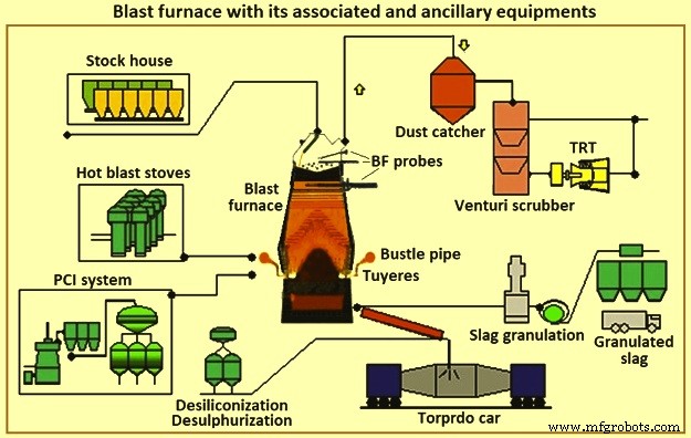
Рис. 1. Доменная печь с сопутствующим и вспомогательным оборудованием
Производство чугуна на доменной печи состоит из системы, состоящей из нескольких компонентов, которые работают в гармонии. Надлежащее применение и эксплуатация этих компонентов необходимы для поддержания процесса производства чугуна. Выбор конкретных компонентов зависит от таких факторов, как существующие условия, физические ограничения, производственные требования, стоимость, график, надежность и ремонтопригодность. Взаимозависимость компонентов так же важна для успешной работы системы, как и их индивидуальные возможности. Существуют основные требования и «нормальные» практики для каждой области или компонента. Существуют также некоторые коммерчески доступные альтернативные технологии, которые имеют присущие им преимущества и недостатки.
ДП превращает железосодержащую рудную шихту в жидкий чугун (жидкий чугун). С доменной печью связаны коксовые батареи, которые перерабатывают уголь в кокс, а также аглофабрики и фабрики по производству окатышей, которые подготавливают железную руду для доменной печи. ДП превращает это подготовленное сырье в более ценный продукт. Чугун из некоторых доменных печей используется в литейных цехах для производства чугунных отливок. Другие операции производят чугун с низким содержанием кремния, который превращается в сталь в сталеплавильном цехе. Часть горячего металла превращается в чугун в машинах для разливки чушек. Побочными продуктами доменной печи являются шлак, колошниковый газ доменной печи, колошниковая пыль и фильтровальная корка. Эти побочные продукты могут иметь как положительное, так и отрицательное экономическое влияние, в зависимости от местных возможностей использования.
Некоторыми из нескольких аспектов, влияющих на каждое рассмотрение при проектировании или реконструкции доменной печи, являются (i) прибыль, (ii) здоровье и безопасность сотрудников, (iii) охрана окружающей среды, (iv) законодательные нормы, (v) потребности предприятия. рынок и последующая переработка, (vi) доступные человеческие ресурсы, ресурсы для строительства и обслуживания, (vii) изменение технологий и устаревание оборудования, (viii) доступное сырье, коммунальные услуги и другие материалы и (ix) так далее. Любое серьезное ограничение в любом из этих аспектов может поставить под угрозу жизнеспособность доменной печи (или даже сталелитейного завода) или сделать невозможным или необходимым строительство новой доменной печи.
БФ обычно группируются по размеру. Мини-ДП производят менее 1500 тонн чугуна в сутки (т ТМ/сутки), малые ДП производят от примерно 2500 т ТМ/сутки до 5000 т ТМ/сутки, средние ДП производят от примерно 6000 т ТМ/сутки до 8000 т ТМ/сутки. т ТМ/день, а крупные ДП производят от 9 000 т ТМ/день до 12 000 т ТМ в день. На интегрированном сталеплавильном заводе для производства чугуна, необходимого для производства стали, требуется несколько и размеры доменных печей. Интегрированные металлургические заводы с несколькими доменными печами менее подвержены влиянию ремонта доменной печи с заменой футеровки или проблем с управлением печью. Небольшие ДП имеют более короткий ремонт по замене футеровки, чем большие ДП, и считаются более простыми в эксплуатации. Однако стоимость чугуна с малых доменных печей выше. Интегрированный сталеплавильный завод должен эксплуатировать минимальное количество экономичных печей. В некоторых случаях производится модернизация с целью сокращения количества работающих печей.
Перефутеровка ДП производится периодически после окончания его кампании (время между ремонтами перефутеровки). В прошлом это включало замену внутренней кирпичной футеровки главной печи. В последнее время обширный ремонт компонентов, замена и профилактическое обслуживание выполняются одновременно. При такой практике более эффективный сталелитейный завод с меньшим количеством больших доменных печей теряет более высокий процент своей продукции во время ремонта футеровки доменной печи, чем завод с большим количеством малых печей. Чтобы иметь как низкие эксплуатационные расходы, так и минимальное вмешательство во время замены футеровки ДП, промышленность работала над максимальным использованием ДП и сокращением продолжительности ремонта по замене футеровки. В настоящее время на интегрированных сталеплавильных заводах наблюдается четкая тенденция к эксплуатации меньшего количества больших печей и использованию технологий и конструкций, которые бесконечно расширяют кампанию доменных печей.
В то же время, снижение изменчивости продукта стало более важным, и, следовательно, делаются инвестиции в автоматизацию, которая улучшает мониторинг и контроль процесса. Операторы доменной печи, обслуживающий персонал, проектировщики и исследовательский персонал применили современные технологии и аналитические методы к процессу доменной печи, чтобы лучше отслеживать и контролировать процесс. В результате стандартное отклонение качества чугуна было снижено. Усовершенствованные системы сбора данных также предоставляют больше информации поставщикам и производителям. Это улучшило выбор материалов и конструкцию доменных печей и сопутствующего оборудования. Продолжительность кампаний увеличилась с 5 до 10 лет примерно до 20 лет.
Производство чугуна на доменной печи — это технология, которой более 430 лет. Несмотря на это, использование доменного чугуна по-прежнему является наиболее распространенным методом, используемым на сталелитейных заводах для производства стали. Современные интегрированные сталелитейные заводы полагаются на доменную печь, которая обеспечивает предсказуемое количество чугуна стабильного качества в соответствии с графиком. Изменение любого из аспектов подачи чугуна оказывает серьезное влияние на остальные процессы производства стали. Таким образом, доменная печь продолжает оставаться ключевым процессом на современных интегрированных сталелитейных заводах.
Иногда утверждается, что технология доменной печи подходит к концу. Это не так. Изучение данных эксплуатации за 23 года (с 1970 по 1993 г.) на типичной паре ДП среднего размера показало, что средний рост производительности составляет 3 % в год (рис. 2а). При этом среднее снижение расхода топлива составило 1 % в год (рис. 2б). Кроме того, продуктивное время между заменой футеровки доменной печи (кампанией) было увеличено за счет улучшения оборудования, материалов и конструкции. В результате общая себестоимость производства чугуна с поправкой на инфляцию улучшилась даже больше, чем показывают операционные данные. Следовательно, технология доменного производства не умерла, хотя ей уже более 430 лет. Он по-прежнему прогрессирует во всех областях значительными темпами. Сегодня БФ остается динамичной наукой, поддерживаемой постоянно совершенствующимися технологиями.
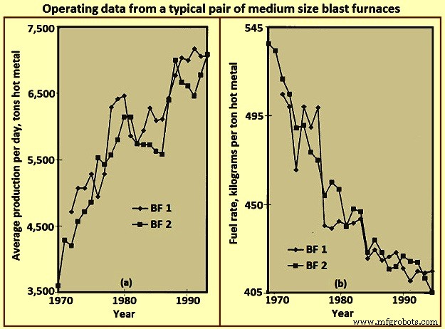
Рис. 2. Рабочие данные типичной пары доменных печей среднего размера
Макет BF
Компоновка доменной печи, по сути, представляет собой интеграцию оборудования, необходимого для обработки различных материалов, необходимых для производства жидкого чугуна, а также получаемого продукта и побочных продуктов. Наиболее эффективная конструкция надлежащим образом соответствует всему процессу, и ее эффективность оценивается с точки зрения как первоначальных капиталовложений, так и текущих эксплуатационных расходов. Компоновка доменного цеха зависит от нескольких факторов, таких как (i) рельеф участка, (ii) климатические условия, (iii) способ доставки сырья, (iv) системы и места обработки сырья на заводе, (v) последующие системы обработки и местоположения, (vi) требования к количеству/потоку жидкого металла, (vii) тип и размер флота для доставки жидкого металла и (viii) так далее. На рис. 3 показана упрощенная схема доменной печи.
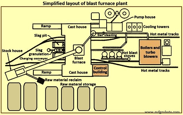
Рис. 3. Упрощенная схема доменного производства
ДП обычно состоит из нескольких секций. Этими секциями являются (i) хранение, обработка и регенерация сырья, (ii) склад, (iii) система загрузки, (iv) собственно печь, (v) литейный цех, (vi) переработка и транспортировка шлака, (vii) обработка горячего металла, (viii) воздухонагреватели и система горячего дутья, (ix) установка газоочистки, (x) коммунальные услуги, (xi) система автоматизации и управления, (xii) средства технического обслуживания и (xiii) средства поддержки персонала.
Хранение сырья и обращение с ним
Сырье, такое как железная руда, агломерат, окатыши, флюсы, уголь, кокс и т. д., поступает либо из внешних источников, либо производится на интегрированном металлургическом заводе. Это сырье нуждается в достаточном количестве контролируемых хранилищ для поддержки работы доменной печи. Емкость хранилища необходима на случай предсказуемых или непредсказуемых сбоев в доставке. Дополнительные складские мощности могут потребоваться в случае возможных изменений в источнике определенного сырья. Необходимы отдельные места для хранения из-за различных физических или химических характеристик аналогичных материалов. Смешивание сходных материалов может привести к проблемам с управлением технологическим процессом/металлургическими проблемами. Складские сваи должны быть разделены, чтобы предотвратить смешивание разнородных материалов. Сваи должны быть размещены на подготовленных основаниях, чтобы операторы оборудования для регенерации сырья могли различать первичный материал и вторсырье. Сваи укладываются таким образом, чтобы свести к минимуму разрушение материала и предотвратить захват мелких частиц ветром. Можно использовать водяные струи и средства для создания кокона, чтобы свести к минимуму захват и унос пыли ветром.
Существует несколько различных методов укладки и извлечения сырья. Методы укладки включают в себя опрокидывание вагонов, мосты для руды, укладочные конвейеры, скребки и т. д. Методы извлечения включают в себя роторные реклаймеры, гибочные реклаймеры, фронтальные погрузчики, скребки, непосредственно со дна бункера или штабеля и т. д. Очевидно, что укладка и извлечение размеры систем должны обеспечивать пропускную способность, необходимую для доменной печи.
Склад
Склад представляет собой складское помещение оператора доменной печи для непосредственной подачи шихты в печь. Бункеры для хранения предусмотрены для каждого из шихтовых материалов для доменной печи. Для одинаковых материалов (например, агломерата, окатышей) с различными металлургическими свойствами предусмотрены отдельные бункеры. Склад обеспечивает достаточную вместимость для различных шихтовых материалов в случае краткосрочных перебоев с поставками со складов сырья. Типичная пропускная способность бункера склада в случае потери подачи сырья составляет (i) кокс – от 2 до 8 часов, (ii) железосодержащие материалы (руда, агломерат и окатыши) – от 4 до 16 часов, и флюсы и другие разные материалы – от 8 часов до 24 часов. Эти мощности основаны на номинальной производительности печей и варьируются в зависимости от надежности и времени доступа для их замены со склада или от поставщика.
Нагрузочные материалы имеют тенденцию к деградации из-за климатических условий и многократного обращения с ними. Чем выше количество операций с материалом (складирование, регенерация, отсыпка, конвейерные желоба, рудные мостовые ковши и т. д.), тем выше процент мелочи в шихте. Процесс BF требует контролируемой проницаемости и, следовательно, контролируемой нагрузки. Загрузка избыточной мелочи, как правило, в течение всей загрузки, либо сосредоточенная в течение определенных коротких периодов загрузки, может нарушить процесс доменной печи и повредить оборудование печи. Склад обеспечивает последнюю разумную возможность удаления мелочи перед загрузкой в печь. По возможности после бункеров хранения кокса, руды, агломерата и окатышей устанавливаются вибрационные грохоты для удаления большей части мелочи. Удаленные мелочи собираются для переработки. Некоторые операторы доменных печей загружают мелкие частицы в определенные участки печи, чтобы регулировать местную проницаемость печи и контролировать тепловую нагрузку на стенки печи.
Влагомеры часто устанавливаются на складе для контроля фактического количества воды, загружаемой в печь. Эта информация позволяет корректировать объемы загрузки, чтобы компенсировать изменяющиеся условия окружающей среды (например, более высокую влажность кокса в период дождей).
Поскольку для поддержания непрерывной работы доменной печи необходимы различные типы и различные количества шихтового материала, шихтовые материалы должны подаваться в определенной последовательности (которая сама по себе может часто меняться для поддержания различных рабочих параметров печи). Следовательно, склад должен быть оснащен надежным оборудованием для извлечения и подачи точного количества конкретных шихтовых материалов для соблюдения определенного графика. На рис. 4 показано упрощенное расположение оборудования на складе.
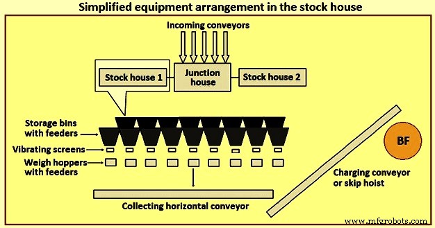
Рис. 4. Упрощенное размещение оборудования на складе
Ранее наиболее распространенным типом стокового дома был тип хайлайн. Этот тип склада расположен непосредственно рядом с печью. Железнодорожные вагоны или мостовые краны загружают бункер для хранения, в то время как бункеры для хранения загружаются непосредственно в тележку для передвижных весов. Оператор тележки с весами вручную управляет разгрузочной заслонкой бункера, чтобы подавать определенное количество материала в оснащенный весами бункер, расположенный в тележке с весами. После сбора надлежащего типа и количества материала оператор перемещает тележку с весами в положение над «скиповой ямой» и сбрасывает шихту через желоб в ожидающую скиповую тележку. Затем скиповая тележка поднимается на вершину печи.
Складской склад высокого типа в сочетании с тележкой-весом предлагает несколько вариантов обеспечения просеивания железистой шихты (руды, агломерата и окатышей). По мере расширения знаний о процессе доменного производства появились более строгие требования к шихте. Концепция «инженерной нагрузки» сегодня хорошо известна в отрасли. Принято считать, что существуют пределы гибкости и приспособляемости склада хайлайн для выполнения этого требования. Таким образом, хайлайновый тип склада был заменен автоматизированным конвейерным складом для подачи шихтовых материалов на доменную печь.
Автоматизированный склад обычно бывает двух разных типов. Первый тип – это замена весовой тележки под бункерами сырья системой питателя и ленточного конвейера. Для каждого вида сырья (кокса, железосодержащих материалов, флюсовых материалов и добавок и т. д.) предусмотрены отдельные конвейеры, над которыми установлены ряды накопительных бункеров, с вибрационными питателями для выгрузки шихтовых материалов из накопительных бункеров на конвейеры. Для материалов, содержащих кокс и железо, на выходе каждого конвейера расположен вибрационный грохот, который просеивает материал и подает просеянный материал в весовые бункеры. Этот тип системы по-прежнему загружает весовые бункеры перед скиповыми вагонами.
Второй тип автоматизированного склада представляет собой большую конструкцию из складских бункеров, построенную полностью над землей и вдали от доменной печи. Обычно это делается для доменных печей, где для подачи шихтовых материалов наверх печи используется ленточный конвейер вместо скиповых вагонеток. Наполнение складских бункеров обычно осуществляется с помощью ленточной конвейерной системы. Сырье подается из накопительных бункеров вибрационными питателями и ленточными конвейерами в весовые бункеры. Весовые бункеры, в свою очередь, выгружают материал на главный конвейер с помощью сборного конвейера. Весовые бункеры запрограммированы на взвешивание сырья в правильном порядке на основной конвейерной ленте к верхней части печи.
Предоставление автоматизированного склада может обеспечить более эффективную подачу сырья на склад и более эффективный отбор, просеивание, взвешивание и доставку шихты в печь. Автоматизированный штабелеукладчик может располагаться непосредственно рядом со скиповым вагоном для подачи в печь или может быть расположен на удалении от печи для загрузки по ленточному конвейеру.
Автоматизация склада значительно увеличила производственные мощности, повысила эффективность работы и устранила отклонения в работе, вызванные операторами и оборудованием. Однако на практике современный автоматизированный склад может быть довольно сложным. Сам склад может питаться конвейерами, которые, в свою очередь, разгружаются на разгрузочные конвейеры для распределения материалов по различным бункерам. Компоновку конвейеров и оборудования в складском помещении можно организовать множеством способов. Размещение склада рядом с печью часто приводит к перегруженности планировки и ограничивает гибкость для будущих модификаций.
Подъемная система
Шахтные материалы обычно поднимаются на вершину доменной печи с помощью скиповых вагонеток или ленточного конвейера.
Пропустить подъем автомобиля – Использование скиповых вагонов для доменной печи пришло из горнодобывающей промышленности. Размеры скиповых вагонеток доменной печи соответствуют пропускной способности печи. Очевидно, что несколько факторов, таких как грузоподъемность подъемника, конструкция скипового моста и т. д., по-своему влияют или ограничивают размер скипа.
Обычно два скипа работают противоположным образом (для уменьшения необходимой подъемной силы) на общем подъемнике. Скипы перемещаются по рельсам на скиповом мосту, обычно устанавливаемом под углом от 60 до 80 градусов от горизонтали. Полный скип медленно ускоряется, когда он покидает скиповую яму, ускоряется как можно быстрее, достигая и перемещаясь с максимальной скоростью на протяжении большей части подъема. Подъемник замедляет движение скипа по мере его приближения к вершине скипового моста. Колеса скипа направляются опрокидывающими и роговыми рельсами, когда скип опрокидывается в загрузочное оборудование колошника. Когда подъемный скип достигает конечной точки разгрузки и останавливается, пустой скип (опускающийся с той же скоростью) как раз достигает дна своего пути в скиповую яму, ожидая заполнения. Система скиповой загрузки является надежным и эффективным способом доставки шихты на колошник. Однако ему не хватает гибкости для оператора, поскольку скипы могут вмещать только определенное количество материала (перегрузка приводит к переполнению или чрезмерной нагрузке на подъем) или становится неэффективным, если требуются небольшие объемы определенного груза. На рис. 5 показана схема подъема скипового вагона.
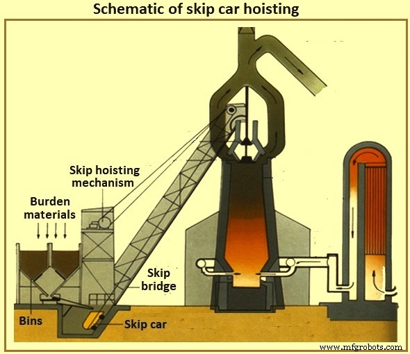
Рис. 5. Схема подъема скипового вагона
Конвейер загрузки печи – С конвейеризацией склада пришла конвейеризация подъемной системы. В настоящее время складские помещения обычно располагаются вдали от печи, и одна большая конвейерная лента доставляет шихту к верхней части печи. Если верх печи имеет высоту около 60 метров, то конвейерная лента, установленная под углом 8 градусов к горизонтальному положению, складское помещение должно располагаться на расстоянии не менее 427 метров от печи. Обычно избегают более крутых наклонов ленты, чтобы свести к минимуму откат материала. Разнообразные материалы обычно загружают непосредственно над и после окончания загрузки железа на ленточном конвейере, чтобы удерживать железосодержащие материалы на месте, пока они не достигнут верхней части печи.
Система загрузки в верхней части печи
Собственно печь работает при положительном высоком верхнем давлении. ДП-газ, состоящий частично из окиси углерода, двуокиси углерода и азота, образуется в процессе доменной печи вместе с большим количеством уносимой пыли. Оператор доменной печи должен поддерживать максимальное давление из-за преимуществ процесса и удерживать газы и пыль (как в целях экономии топлива, так и в целях контроля окружающей среды). Тем не менее, оператор должен регулярно размещать шихтовый материал в верхней части печи, чтобы пополнять внутренний процесс, не теряя давления в верхней части печи.
Верх колокольчика – В течение нескольких лет наиболее распространенным типом колошника был двухконусный колпак (рис. 6). Когда шихта достигает верха печи (по скипу или по конвейеру), она падает в приемный бункер и в малый конусный бункер. Небольшой колпак (стальная отливка конической формы диаметром около 2,6 м и высотой 1,4 м для доменной печи производительностью 5000 тонн твердого металла в день) опускается и позволяет шихте падать в большой конусный бункер. Небольшой колокол поднимается и прижимается к неподвижному сиденью на бункере для малых колоколов. В зависимости от объема большого конусного бункера дополнительные загрузки шихты последовательно подаются в большой конусный бункер с помощью малого колокола. На протяжении всего этого процесса большой колпак оставался закрытым, закрывая печь. Когда правильное количество загрузки шихты собрано, большой колокол (стальная отливка конической формы диаметром около 5,5 м и высотой около 3,5 м для доменной печи производительностью 5000 тнм в день) опускается и позволяет шихте скользить вниз по колоколу в собственно верх печи. После разгрузки шихты большой колокол поднимается и плотно прилегает к нижней части бункера большого колокола. На рис. 6 показаны системы верхней загрузки BF колокольного типа.
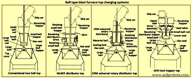
Рис. 6. Системы загрузки доменной печи колпакового типа
Очевидно, что управление распределением шихты с печью для этого типа колошника ограничивается тем, насколько равномерно шихта укладывается на большой колпак (сброс скипа приводит к неравномерному размещению шихты в этом типе колошника) и кривыми падения шихты. конкретные материалы шихты (например, кокс или железная шихта), когда они соскальзывают и падают с большого колпака. Кроме того, верхняя часть с двумя раструбами подвержена потере герметичности большого и малого раструбов и уплотнения между стержнем большого раструба и трубкой малого раструба. Утечка в колоколе происходит из-за истирания шихтовым материалом, скользящим по уплотняющим поверхностям колокола. Утечка в уплотнении стержня является результатом истирания мелких частиц либо внутри печи, либо из-за их скопления на большом раструбном стержне после сброса шихты в приемный бункер.
Чтобы свести к минимуму износ большой уплотняющей поверхности колпака, газ BF, взятый из печи, вводят между колпаками для выравнивания пространства (уменьшая перепад давления на большой уплотняющей поверхности колпака). Этот газ сбрасывается в атмосферу перед открытием небольшого колпака, чтобы можно было ввести больше нагрузки. Ниже приведены некоторые варианты, позволяющие улучшить ограничения системы с двумя раструбами.
Дистрибьютор McKEE – Распределитель McKEE (рис. 6) в течение нескольких лет был основным усовершенствованием распределения нагрузки, доступным для верхней части с двумя раструбами. Однако его быстро вытесняют другие технологии. Его конструкция включает в себя возможность вращать малый колокол и малый бункер вместе во время разгрузки скипового вагона. Нагрузка равномерно распределяется в бункере малого колокола, что улучшает равномерное размещение груза на большом колоколе. Этот тип верхней части подвержен износу малых и больших раструбов и последующей потере герметизирующего эффекта.
Крышка универсального поворотного распределителя CRM – Универсальный роторный распределитель CRM (Centre Recherches Metallurgiques – Бельгия) (рис. 6) был разработан для устранения потери эффекта уплотнения малого колпака. Вместо обычного малого колокола устанавливаются два колокола (герметизирующий и материальный). Вращающийся загрузочный бункер установлен на колоколе материала. Уплотнительный колпак расположен под колпаком для материала и уплотняет неподвижное седло. Во время разгрузки скипа загрузочный бункер и закрытый колпак для материала вращаются для равномерного заполнения бункера. Когда заполнение завершено, вращение бункера прекращается. Когда приходит время высыпать на большой колпак, вращающийся бункер, колпак для материала и герметизирующий колпак опускаются. Уплотнительный колпак опускается ниже фиксированного седла. В середине процесса опускания опускание бункера останавливается, а конус для материала и уплотнительный конус продолжают опускаться до тех пор, пока не достигнут положения остановки. По мере открытия зазора между конусом для материала и бункером шихта равномерно выгружается в большой бункер. Когда шихта выходит из зазора, она не соприкасается с посадочной поверхностью уплотняющего клапана, что обеспечивает максимальную герметизирующую способность. Этот тип верхней части способен выдерживать внутреннее давление 0,2 МПа.
Верхняя часть CRM улучшает герметизирующие свойства и долговечность двух раструбной крышки. Однако он не обеспечивает значительного улучшения распределения шихты печи по сравнению с распределителем McKEE и не устраняет уязвимость большой уплотнительной поверхности колпака.
Крышка бункера с замком GHH – Крышка бункера с замком GHH (рис. 6) является модификацией крышки с двумя воронками. Это снижает зависимость от большого колпака для поддержания газового уплотнения. Добавление запорных бункеров с отдельными запорными клапанами для каждого места сброса скипа обеспечивает дополнительную возможность герметизации верхней части. Большой колпак может работать без перепада давления на его уплотняющей поверхности (т. е. давление в верхней части печи равно давлению в бункере большого колпака). Операция приведена ниже.
Скип сбрасывает груз шихты в бункер шлюза через приемный бункер и открытый запорный клапан. Нагрузка размещается на вращающемся маленьком колпаке и равномерно заполняет вращающийся бункер-распределитель над малым колпаком. Уплотнение между воронкой-замком и вращающейся воронкой-колоколом открыто во время вращения. Когда выгрузка шихты из скипа завершена, запорный клапан и уплотнение между шлюзовым бункером и малым конусным бункером закрываются. Вводится уравнительный газ, и в запорной воронке создается давление до верхнего предела печи. Затем небольшой колокол опускается, чтобы поместить груз в большой бункер. Небольшой колпак закрывается, и давление из бункера шлюза сбрасывается до атмосферного. Запорный клапан на противоположной стороне (т. е. в другом положении разгрузки скипа) открыт. Открывается уплотнение между воронкой-замком и воронкой-колоколом. Начинается вращение малого колокола и бункера. Верх теперь может принимать нагрузку от другого скипа.
Этот тип верхней части улучшает герметизирующие свойства и долговечность двухконтурной верхней части. Однако верхняя часть бункера с замком не обеспечивает значительного улучшения распределения шихты печи по сравнению с верхней частью McKEE или CRM. Хотя большой колпак больше не нужен для выполнения функции герметизации, долговечность эффекта герметизации маленького колпака по-прежнему имеет решающее значение.
Подвижная броня – Важным шагом, предпринятым для улучшения распределения нагрузки на вершину колоколообразного типа, стала разработка подвижной брони (рис. 7). В горловине печи установлены регулируемые дефлекторы для отклонения шихты после ее соскальзывания с большого колпака. Подвижная броня регулируется в зависимости от конкретной выгружаемой шихты и того места, где оператор хочет разместить шихту внутри печи.
Несколько производителей предоставляют различные типы подвижной брони. Отдельные сегменты брони можно перемещать равномерно (одновременно и одинаково) внутри печи, чтобы разместить шихту в виде кольца. Доступны другие типы подвижной брони, обеспечивающие индивидуальное управление пластинами брони для достижения некруглой схемы распределения.
Некоторыми недостатками, связанными с подвижной броней, являются (i) большинство механических и изнашиваемых компонентов связаны с суровыми условиями конуса колошника печи, (ii) необходима некоторая потеря внутреннего рабочего объема для обеспечения зазора между подвижной броней и расчетной линией запаса. уровне (хотя эта зона печи не может быть отнесена к зоне грубой производительности с учетом рабочего объема печи и (iii) ограниченной способности отклонять шихту в самый центр печи, особенно когда уровень запаса уже высок. характеристика пуль часто сводит на нет ограниченное перемещение подвижной брони.
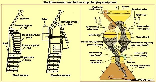
Рис. 7. Броня приклада и бесконусное загрузочное оборудование
Система верхней зарядки без колокола – В начале 1970-х компания Paul Wurth S.A. из Люксембурга разработала систему зарядки без раструба (BLT) (рис. 7). Этот тип колошника радикально отличается от колпакового колпака. Нагрузка может быть размещена внутри печи в любом порядке, необходимом оператору печи. Кольцевые кольца, спирали, сегменты и точечное размещение являются обычными схемами, достигаемыми синхронным или независимым наклоном и вращением желоба для распределения шихты, расположенного с верхним конусом печи.
Герметичность свода печи сохраняется на протяжении всей кампании печи. Мероприятия по техническому обслуживанию просты и непродолжительны. Обычно БЛТ состоит из приемного желоба или бункера (принимающего шихту из скипов или с конвейерной ленты), затворного бункера с верхним и нижним запорными клапанами, заслонки управления потоком материала, редуктора привода главного желоба (водяного или газового -охлаждаемый узел, используемый для поворота и наклона желоба), и желоб для распределения шихты. Существует три основных типа BLT, а именно (i) параллельный бункер, (ii) центральная подача и (iii) компактный тип.
Как правило, параллельный тип включает в себя два шлюзовых бункера (бункеры были установлены на некоторых печах для пропускной способности и в целях резервирования; один «эксцентрический» тип бункера был установлен для приложений с ограниченным зазором). С начала 1980-х годов несколько доменных печей выбрали тип бункера с одинарным затвором с «центральной подачей» из-за улучшенного разделения шихты и контроля распределения шихты, что привело к улучшению работы печи.
«Компактный» тип колошника BLT был разработан для печей малого и среднего размера, чтобы позволить использовать BLT (и его преимущества) в печах, где другие более крупные типы BLT не могут использоваться из-за стоимостных или физических ограничений. Этапы работы BLT для типа с центральной подачей:(i) шихта выгружается из скипа или конвейерной ленты через приемный желоб или бункер через открытый запорный клапан в бункер шлюза, (ii) после приема шихты в шлюз затвора, верхний запорный клапан закрывается и вводится уравнительный газ для повышения давления в затворном бункере до давления в топке, (iii) нижний запорный клапан открывается, (iv) шихта выгружается из запорного бункера, когда заслонка для материала установлена на предварительно выбранное отверстие в соответствии с конкретным выгружаемым материалом шихты, (v) шихта падает вертикально через желоб питателя с коробкой главной передачи и падает на желоб распределения шихты, (vi) желоб распределения шихты направляет шихту в нужное point(s) within the furnace, (vii) when the lock hopper is fully discharged (monitored by load cells and / or acoustic monitoring), the lower seal valve is closed, (viii) a relief valve is opened to exhaust the lock hopper to atmosphe re (or through an energy recovery unit), and (ix) the upper seal valve opens and the sequence is repeated.
The advantages of BLT over other top charging systems include higher top pressure capability (i.e. 0.25 MPa), fuel savings, increased production, more stable operation, reduced maintenance in terms of cost and time, increased furnace campaign life, and improved furnace operational control when employing high coal injection rates at the tuyeres.
Gimbal system of charging – The purpose of the Gimbal system of charging is to facilitate controlled distribution of charge material into the BF via a Gimbal type oscillating chute through a holding hopper and variable material gate opening such that the pressurized charging system above can operate independently of the distribution system. It utilizes a conical distribution chute, supported by rings in a Gimbal arrangement, producing independent and combined tilting of the chute axis. The Gimbal distributor, as part of the overall BF top charging system, offers a fully integrated charging solution, generating considerable improvement in BF operation and maintenance cost. The Gimbal system utilizes a conical distribution chute, supported by rings in a Gimbal arrangement, producing independent, and combined tilting of the chute axis.
The Gimbal top incorporates a full complimentary range of furnace top distribution equipment including distribution rockers, upper seal valves, hoppers, lower seal valves, material flow gates and goggle valve assemblies, all discharging through hydraulically driven distribution chutes. The tilting chute is driven by two hydraulic cylinders, mounted 90 degree apart. This type of suspension and drive arrangement results not in a rotation of the tilting chute, but in a circular path by superposition of both tilting motions. Independent or combined operation of the cylinders allows the chute axis to be directed to any angle, or even along any path. Motion is supplied by two hydraulic cylinders, each operating through a shaft, connecting rod, and universal joint in order to drive the Gimbal rings. Through the movement of the hydraulic cylinders, the distribution chute allows precise material distribution with potential for an infinite number of charging patterns at varying speeds. These include ring, spiral, centre, spot, segment or sector charging, providing complete control of material charging into the furnace.
The whole distributor assembly is enclosed in a gas tight housing, which is mounted directly onto the top flange of the BF top cone. The housing contains a fixed inlet chute and a tilting distribution chute supported by rings in a Gimbal arrangement allowing independent and combined tilting of the chute axis. The assembly is made from a combination of stainless and carbon steel material with the fixed inlet chute and tilting chute body lined with ceramic material to give superior wear protection. A closed-circuit water cooling system supplies cooling water through the main shafts, Gimbal bearings, and universal joint bearings in order to cool the moving elements of the Gimbal distribution system.
The key features of the Gimbal design are (i) simple, rugged design, using levers driven by the hydraulic cylinders, (ii) drive cylinders are mounted outside pressure envelope, hence not subject to hot and dusty service conditions, (iii) Gimbal ring arrangement gives simple tilting motion in two planes, which when superimposed gives 360 degrees distribution, and (iv) wear on the tilting chute is equalized around its circumference giving a long extended operational life.
The BF Gimbal top is an automated, computer-controlled pressurized charging system designed to (i) receive charges of ore, coke, and miscellaneous materials in the holding hopper, independently of the distribution system below, (ii) release those discharges, as needed, to a dynamic distribution chute located below the holding hopper, and (iii) distribute material in prescribed patterns to the furnace stock-line in accordance with a predetermined charging matrix. Control of the Gimbal distribution chute is fully integrated into the overall furnace charging software. The system provides a high level of accuracy and control for the Gimbal movements and hence the positioning of the distribution chute. Gimbal material distributor is shown in Fig 8.
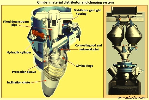
Fig 8 Gimbal material distributor and charging system
Furnace proper
The furnace proper is the main reactor vessel of the BF ironmaking process. Its internal lines are designed to support the internal process. Its external lines are designed to provide the necessary systems to contain, maintain, monitor, support, and adjust the internal process.
The BF process is a counter flow process. The process comprises of (i) burden at ambient conditions is placed in the furnace top onto the column of burden within the furnace, (ii) as the burden descends with the burden column, it is heated, chemically modified, and finally melted, (iii) further chemical modifications occur with the molten material, (iv) the molten products are extracted near the bottom, (v) melting of the burden material and extraction result in the descent of the burden column and the need for replenishment of the burden at the top, (vi) hot blast air is introduced through tuyeres near the bottom, (vii) BF gases are generated in front of the tuyeres and ascend through the burden and chemically modify the descending burden as well as themselves get chemically modified and cooled, (viii) BF gas (and dust) is extracted near the top of the furnace, and (ix) heat is extracted from the vessel in all directions (primarily through the lining cooling system) and along with the BF gas, liquid iron and liquid slag. Fig 9 shows cross section and types of BF.
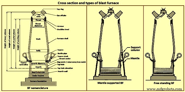
Fig 9 Cross section and types of blast furnace
Furnace type – Furnaces are constructed to be mantle supported or free standing. Mantle supported BFs characteristically have a ring girder (mantle) located at the bottom of the lower stack of the furnace. The mantle is supported in turn by columns which are on the main furnace foundation. The hearth, tuyere breast, and bosh are also supported by the foundation. Furnaces with mantle support column tend to have restricted access and reduced flexibility for improvements in the mantle, bosh, and tuyere breast areas.
Since thermal expansion is a major consideration in furnace shell design, the mantle style of furnace provides an interesting design consideration. The mantle support columns are relatively cool. The mantle tends to maintain a constant height, throughout the furnace campaign with respect to the furnace foundation. Thermal expansion of the stack due to process heat is considered to be based at the ‘fixed’ mantle (i.e. the top of the furnace raises with respect to the mantle). The effective height of the bosh, tuyere breast, and hearth wall shells (supported on the furnace foundation) increases due to the thermal expansion of the shell caused by the process heat. The lower portion of the furnace lifts upwards towards the fixed mantle. Hence, the provision of an expansion joint of some type is needed at the bosh / mantle connection or somewhere appropriately located in the lower portion of the furnace.
Free standing furnaces have been developed to eliminate the column and permit the installation of major equipment and furnace cooling improvements. This furnace type has a thicker shell for structural support. Installation and maintenance of a reliable cooling and lining system is necessary in order to sustain the structural longevity of the shell.
Two variations of the free standing furnace have been used. One type provides for a separate structural support tower to carry the furnace off-gas system and charging / hoisting system load. The other type (while it does employ a separate support tower for shell replacement purposes during relines) uses the furnace proper to support the off-gas system and charging / hoisting system loads. Special consideration to the furnace shell design is to be made regardless of the furnace type. The furnace vessel is subjected to internal pressures from the blast and gas, burden, liquid iron and slag. Dead and live load during all operating, maintenance, and reline stages are to be considered as well.
Furnace zones – The major zones of the furnace proper are (i) top cone, (ii) throat, (iii) stack, (iv) mantle / belly, (v) bosh, (vi) tuyere breast, (vii) hearth walls, (viii) hearth bottom, (ix) foundation.
Top cone – The top cone or dome is the uppermost part of the furnace proper. It supports the furnace top charging equipment, and the BF top gas collection system. Stock rods (stockline recorders or gauges) are normally placed here to monitor the upper level of the burden in the furnace. These devices are the units which provide the permissive or indication signals to charge the next scheduled burden input to the furnace. Typically, they are weights lowered by special winches, or microwave units. Some furnaces incorporate radio-active isotope emitters and detectors mounted in the furnace throat to monitor the burden level. Infrared camera can be installed in the top cone to monitor the BF top gas temperature distribution as it escapes the furnace burden stockline.
The top cone is the coolest zone of the furnace proper but can be exposed to extremely high temperatures if burden ‘slips’ (rapid, uncontrolled burden descent after a period of unusual lack of descent). The newly charged burden falls through this zone and the BF top gas is carried away from this section.
Throat – Steel wear plates or armour are installed in this zone. Here, abrasion of the furnace lining from the charged burden is the prime cause of deterioration. Furnace operators work to maintain the upper level of the burden (the stockline) in this region. Movable armour can be installed in this area in order to deflect the burden falling from a large bell. With the installation of the BLT, wear of the stockline area can be greatly reduced. Some BF users select to eliminate the armour plates and use an abrasion resistant refractory lining instead.
Stack – The stack (sometimes called shaft or the ‘in-wall’) is the zone between the mantle or belly on a free standing furnace and the stockline area. Smooth, uniform lines (the process ‘working surface’) of the stack are essential for uniform and predictable burden descent, BF gas ascent, and stable process control throughout the furnace campaign. Process considerations dictate a larger diameter at the base of the stack than at the top. Typical stack angles are in the range of around 85 degrees from the horizontal.
Mantle / belly – The mantle or belly area provides the transition between the expanded stack and bosh sections. Maintenance of the effectiveness of the cooling / lining system is particularly important for the mantle type furnace in order to protect the mantle structure. Thermal protection is important for the free standing furnace type as well. However, the free standing design is less complicated and more accessible in this area.
Bosh – The bosh area lies between the tuyere breast and the mantle / belly of the furnace. The bosh diameter increases from bottom to top. The inclination of the bosh permits the efficient ascent of the process gases and has been found to be necessary in order to provide the needed zone service life (the process gases are extremely hot and internal chemical attack conditions are severe). Typical bosh angles are in the range of around 80 degrees from the horizontal. Boshes are of two basic types, namely (i) banded and (ii) sealed. They can be cooled by different techniques.
Banded boshes are found in older mantle supported furnaces (they cannot be applied to free standing furnaces). A number of steel bands are placed in incrementally increasing diameters (smallest at the bottom of the bosh and largest at the top) and are tied together with connecting strips. Gap between the bands permits the introduction of copper cooling plates. Ceramic brick lining is to be used as air infiltration results in oxidation of carbon based linings. Gas leakage through the banded bosh can be high. This type is not suitable for BFs with high blast pressure / high top pressure. Banded boshes provide adequate flexibility to eliminate the requirement for a shell expansion joint in the lower portion of the furnace.
Sealed boshes, using continuous steel shell plate instead of separate bands, are employed to permit the use of improved cooling / lining systems, higher furnace operating pressures, and the free standing furnace type. Sealed boshes retain valuable gases with the furnace, hence improving the metallurgical process. As well, the seal bosh, since it precludes air entry into the lining, supports the use of carbon based refractories.
Tuyere breast – Hot blast air is introduced to the furnace through tuyeres (water-cooled copper units) located within the tuyere breast. The number of tuyeres needed depends upon the size (production capacity) of the furnace. The tuyere breast diameter, tuyere spacing, and number of tuyeres are influenced by the expected raceway zone size in front of each tuyere.
Tuyere stocks (Fig 10) convey the hot blast air from the bustle pipe to the tuyeres. The tuyeres are supported by tuyere coolers (water-cooled copper units) which are in turn supported by steel tuyere cooler holders (either welded or bolted to the furnace shell). Special consideration are to be made in the tuyere breast shell and lining design in order to maintain effective sealing of the different components in order to prevent escape and loss of the furnace gases.
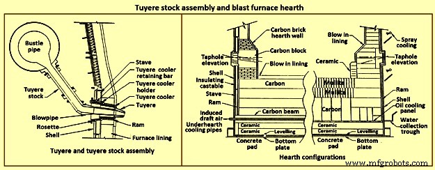
Fig 10 Tuyere stock assembly and blast furnace hearth
Hearth – The hearth (Fig 10) is the crucible of the furnace. Here, hot metal and liquid slag are collected and held until the furnace is tapped. The hearth wall is penetrated by tap holes (frequently called iron notches) for the removal of the collected hot metal and liquid slag. The number of tap holes is dependent upon the size of the furnace, hot metal, and liquid slag handling requirements, physical and capital constraints etc.
Several furnaces are equipped with a slag or cinder notch (normally one per furnace, although some furnaces can have two). The slag notch opening elevation is normally sufficiently higher than the iron notch elevation. In earlier days, when slag volumes were high, the slag was flushed from the slag notch periodically. This simplified the iron / slag separation process in the cast house. More commonly now, however, the slag notch is retained solely for initial furnace set-up procedures or for emergency use in case of iron notch or other furnace operating problems.
Hearth bottom – The hearth bottom supports the hearth walls and is flooded by the iron within the furnace. As the campaign progresses, the hearth bottom lining wears away to a fixed equilibrium point. The remaining refractory contains the process and with sufficient cooling or inherent insulation value protects the furnace pad and foundation.
Cooling system
The application of specific cooling techniques to individual furnace zones is dependent upon several factors such as campaign life expectancy, furnace operational philosophy, burden types, refractories, cost constraints, physical constraints, available cooling media, and preferences etc. Different cooling techniques can be provided for different zones to assist the lining to resist the specific zone deterioration factors. Normally, the provision of adequate cooling capacity is necessary in each of the applicable furnace zones if the lining system located there is to survive. Where the thermal, chemical, and to some extent the abrasive conditions of the process are extreme, sufficient cooling is to be provided to maintain the necessary uniform interior lines of the furnace and to protect the furnace shell.
Typically, the top cone and throat areas of the furnace are not cooled. The hearth bottom can be ‘actively’ cooled by under hearth cooling (air, water, or oil media) or ‘passively’ cooled by heat conduction though the hearth bottom lining to the hearth wall. The basic cooling options for the balance of the furnace are (i) no cooling (typically the upper portion of the stack is not cooled in several furnaces, (ii) shower or spray cooling, (iii) jacket or channel cooling, (iv) plate cooling, and (v) stave cooling.
Shower or spray cooling – Water is directed by sprays or by overflow troughs and descends in a film over the shell plate. Effective spray nozzle design, numbers and positioning are important for proper coverage and to minimize rebound. Proper deflector plate design is necessary to ensure efficient cooling water distribution and to minimize splashing. Shower cooling is frequently employed in the bosh and hearth wall areas. Spray cooling is normally applied for emergency or back-up cooling, primarily in the stack area. Exterior shell plate corrosion and organic fouling are common problems which can disrupt water flow or insulate the shell from the cooling effect of the surface applied cooling. Water treatment is an important consideration to retain effective cooling.
Jacket or channel cooling – Fabricated cooling chambers or indeed structural steel channels or angles are welded directly to the outside of the shell plate. Water flows at low velocity though the cooling elements in order to cool the shell and the lining. Jacket or channel cooling is frequently applied to the hearth walls, tuyere breast, and bosh areas. Scale build-up on the furnace shell and debris collection in the bottoms of the external cooling elements can compromise the cooling effectiveness. Hence periodic cleaning of the cooling elements is necessary.
The critical area of concern in the cooling schemes mentioned so far is the necessity for the shell plate to act as a cooling element. If extreme heat loads are acting upon the inside face of the shell, then there exist an extremely high thermal gradient across the shell. This effect results in high thermally induced shell stresses and eventual cracking. The cracks start from the inside of the furnace and propagate to the outside. The cracks remain invisible (other than a ‘hot spot’) until they fully penetrate the shell plate. Through cracking of the shell plate results in the leak of the BF gas, exposed shell carburization, and disruption of the cooling effect (particularly spray or shower cooling). Shell cracking into a sealed cooling jacket or channel is difficult to locate and can result in long furnace outage time for repair. Entry of water into the furnace (frequently when the furnace is off-line and internal furnace gas pressure cannot prevent entry of cooling water though shell cracks) can have detrimental effect upon the furnace lining. Water in the furnace can be potentially dangerous due to explosion risk (steam or hydrogen). Since shower and jacket cooling rely on the shell plate to conduct the process heat to the cooling media, the plate and stave cooling are configured to isolate the shell from process.
Plate and cigar cooling – Installation of cooling elements though the shell of the furnace (Fig 11) has been a major furnace design improvement resulting in effective cooling of the furnace lining and protection of the shell plate. Cooling is provided along the length of the cooling element penetration into the lining. The inserted elements provide positive mechanical support for the refractory lining. Typical cooling plate manufacture is cast high conductivity copper. Single or multiple passes of cooling water can be incorporated. Cooling boxes with larger vertical section have been produced from cast steel, iron, or copper.
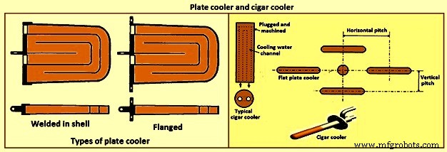
Fig 11 Plate cooler and cigar cooler
Cigar type (cylindrical) coolers (Fig 11) of steel and /or copper have also been successfully used. The philosophy of dense plate cooling (i.e. vertical pitch of 350 mm to 400 mm centre-to- centre, and horizontal pitch of 600 mm (centre-to-centre) has improved the cooling effect and increased lining life.
Copper cooling plates have traditionally been anchored in the shell plate with retainer bars or bolted connections to permit ready replacement if plate leakage occurs. More recently, plates have been designed with steel sections at the rear of the plate for welding directly to the steel shell. While sometimes taking longer to replace, this type provides a positive seal against BF gas leakage. Plate coolers are typically installed in areas above where the liquid iron collects in the furnace. Hence the mid-point of the tuyere breast, right up to the underside of the throat armour is the range of application.
Stave cooling – Cast iron cooling elements (Shannon plates or staves) have been used for several years in the bosh and hearth wall areas. These castings have cored cooling passages of large cross-section. While their service life have been not remarkable in the bosh, multiple campaigns have been normal for the hearth wall. These staves frequently suffered from low flow rates of marginal quality cooling water (scaling and debris deposition / build-up) and sometimes casting porosity. Water leaks into the hearth wall can be a considerable problem.
In the 1950s, the then USSR developed a new type of stave cooler (Fig 12) and ‘natural evaporative stave cooling’. For this design, castings were of gray cast iron containing steel pipes for water passes. The pipes were coated prior to casting to prevent carburization of the cooling pipe and metallurgical contact with the stave body material. The staves were installed in horizontal rows with the furnace and the cooling pipes projected through the shell. Vertical column of staves were formed by the inter-connection of the projecting pipes from one stave up to the corresponding stave in the next row. Staves can be applied to all the walls in the zones below the armour. Staves in the hearth wall and tuyere breast are supplied with smooth faces. Staves in the bosh, mantle / belly and stack normally have rib recesses for the installation of refractory.
Evolution of the stave cooler design has been dramatic. Staves in the higher heat load areas are now typically cast from ductile iron for improved thermal conductivity and crack resistance. While early stave design used castable refractory (installed after stave installation within the furnace), ribs now normally incorporate refractory bricks, either cast in place (with the stave body at the foundry) or slid and mortared in place prior to installation in the furnace. Fig 12 shows stave cooler and generations of stave development.
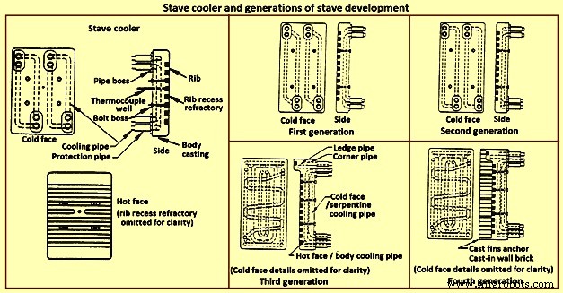
Fig 12 Stave cooler and generations of stave development
Staves are normally expected to retain a refractory lining in front for some time. After loss (expected) of the lining the staves are designed to resist the abrasive effects of descending burden and ascending dirty gas. As well, they are to absorb the expected process heat load and resist thermal load cycling and shock. Four generations of staves (Fig 12) are normally recognized in the industry.
First generation staves are no longer normally used. These staves have four cooling body circuits (with long radius bends which do not effectively cool the stave comers. These staves are made of gray iron castings with castable rib refractory. Second generation staves have four cooling body circuits with short radius bends for improved comer cooling. These staves are made of ductile iron castings with cast-in or glued-in rib bricks. Third generation staves have two-layer body cooling incorporating four or six cooling body circuits (stave hot face) and one or two serpentine cold face circuits (stave cold face) for additional or back-up cooling in the event of hot face circuit loss. These staves have additional edge cooling (top and bottom). The more frequent use of these staves is as cooled ledges to support a refractory lining. These staves have cast-in or mortared-in rib bricks. Fourth generation staves have two-layer cooling (similar to third generation). These staves have cooled ledges and cast-in wall brick lining eliminating the need for a manually placed interior brick lining.
Staves incorporating hot face ledges are more effective in retaining a brick lining than the smoother rib faced bricks. However, once the brick lining disappears, the ledges are very exposed within the furnace. The ledges disrupt burden descent and gas ascent. Exposed ledges tend to fail quickly. They are frequently serviced by cooling water separate from the main stave cooling circuit(s). In this way leaking ledge circuits can be more easily located or isolated. Some stave manufacturers are now providing separate ledge castings so that ledge cracking and loss does not damage the parent staves. As well, there is some present change in philosophy to abandon the application of ledges entirely.
Variations of the basic stave generation types are common. For example, staves of fourth generation type utilizing a refractory castable for the wall ling have been employed successfully. Alternatively, brick linings have been anchored to the stave bodies. Such approaches can be used to substitute for brick support ledges.
A ‘fifth’ generation of staves design has been the developed. It is the copper stave (Fig 13). The development of copper staves was carried out both in Japan and Germany for use in the region of bosh, belly, and lower stack to cope with high heat loads and large fluctuations of temperatures. While Japan has gone for cast copper staves, German copper staves are rolled copper plates having close outer tolerarnces and with drilling done for cooling passages. Drilled and plugged copper staves are typically designed for four water pipes in a straight line at the top and four water pipes in a stright line at the bottom. Materials for internal pipe coils include monel, copper, or steel. Unlike cast iron staves, copper staves are intended to be bonded to the cooling pipe.
The development of the cast-in copper stave has considered the following aspects. As per the first aspect, for the prevention of deformation, appropriate design of the stave length and bolt constrained points is important. The first aspect is that the use of the cast-in steel pipe copper stave with its own design is beneficial for effectively reducing the risk of deformation. Fig 13 shows the constrained points of a rolled copper stave and the cast-in steel pipe copper stave. A rolled copper stave is constrained to the shell by mounting bolts and pins. To prevent the weld at the base of a rising pipe from being damaged by stresses, rising piping is connected to the shell by an expansion joint. Due to this structure, the upper and lower ends of the staves are freely displaced, causing the staves to be easily deformed. The large thermal load which is repeatedly applied to the copper stave in the course of the fluctuation in the BF operations etc., causes plastic strain to be gradually accumulated, and results in large deformation. There are cases in which the deformation at the upper end has reached 50 mm or more and a weld has been broken, under the condition of an overly long stave, an in-appropriate bolt position, or high heat load exceeding the design condition.
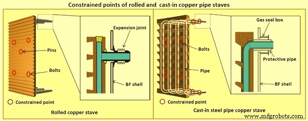
Fig 13 Constrained points of rolled and the cast-in pipe copper stave
Presently, the most popular type of copper stave is the rolled copper stave, the manufacturing process of which involves drilling holes on a copper plate. The water channel ends of these staves are plug-welded. The cast-in steel pipe copper stave, which has been developed, is made by casting bent steel pipes into the copper, a completely different manufacturing process from that of the conventional rolled copper stave. This unique manufacturing method has enabled achieving high energy efficiency and long life of BFs, which cannot be achieved using the rolled copper stave.
Natural evaporative stave cooling (NEVC) is a technique where boiler quality water is introduced into the bottom row of staves and flows by natural mean up the vertical cooling circuits. As the process heat conducts through the stave and cooling pipe into the water, the water in turn heats up. As the water warms, it expands. Since cooler water is being introduced below, the warm water tends to move upwards. At some point in the vertical cooling circuit, the water is at the boiling point. As the water changes its phase to steam, due to the latent heat of vapourization, additional heat is absorbed (driving the phase change). After boiling begins, two-phase flow (water and steam mixture) ascends the cooling pipes to the top of the furnace. Normally located on the furnace top platform are steam separator drums used to extract and vent the steam to atmosphere. Make-up water is introduced to the drum (to replace the discharged steam). The water is piped back by gravity to the furnace bottom and is fed once more to the staves. This cooling technique is very efficient and has low operating costs. There is no pumping equipment. The improvements in this system has been to boost the flow of the cooling water with recirculating pumps (forced evaporative cooling, FEVC) in order to ensure uniform cooling water flow and to cool the recirculating water (forced cold water cooling – FCWC). Both of these approaches have resulted in improved stave and lining life.
Staves provide an excellent protection for the shell plate throughout their service life (which is extended while the interior brick lining remains in place). Stave application has been implemented in all areas of the furnace from hearth wall up to and including the upper stack.
One drawback for conversion of an existing plate cooled furnace to stave cooling can be the cost of a new shell. However, if the existing shell is already in distress and is to be replaced in any event, the conversion cost is not a major factor.
Cast house
The cast house (Fig 14) is the area or areas at the BF where equipment is placed to safely extract the hot metal and liquid slag from the furnace, separate them, and direct them to the appropriate handling equipment or facilities. The hot metal and liquid slag are removed from the furnace through the tap hole. Only infrequently today slag is flushed from the slag notch. The equipment for tap hole is to be reliable and need minimum maintenance. Furnaces typically tap eight times to eleven times per day.
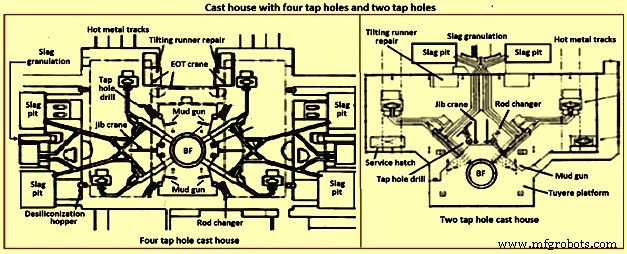
Fig 14 Cast house with four tap holes and two tap holes
Mud gun – The mud gun is used to close the tap hole after tapping is complete. A quantity of the tap hole mass is pushed by the mud gun to fill the worn hole and to maintain a quantity of the tap hole mass (the mushroom) within the hearth. The mud gun is normally held in place on the tap hole until the tap hole mass cures and the tap hole is securely plugged. A hydraulic mud gun uses hydraulic power to swing, hold, and push the tap hole mass. Typical injection pressure of tap hole mass is of the order of 20 MPa to 25 MPa, permitting it to push viscous mass into the furnace operating at high pressures. The hydraulic gun is held against the furnace with the equivalent of 15 tons to 35 tons of force. This type of mud gun can be swung into place in one motion.
An electro-mechanical gun has three separate electric drives for unit swing, barrel positioning, and ramming. Hence several separate motions are needed for accurate positioning of the mud gun at the tap hole. Tap hole mass injection pressure is in the range of only 5 MPa to 8 MPa. The electro-mechanical mud gun is latched to the furnace to keep it in place during plugging.
Tap hole drill – Tap hole drill is used to bore a hole though the tap hole clay into the hearth of the furnace. A drill unit is swung into place hydraulically and held hydraulically in the working position. A pneumatic motor feeds the hammer drill unit (with an attached drill rod and bit) into the hole. Compressed air is fed down the centre of the drill rod and the drill bit to cool the bit and blowout the removed tap hole mass. When the tap hole drill rod has penetrated into the hearth, the drill rod is retracted and the drill swings clear of the hot metal stream.
Soaking bar technique – The application of the soaking bar practice has improved the tapping process. When the tap hole mass is still pliable after plugging, a steel bar is driven into the tap hole by the tap hole drill. While the bar sits in place during the time between casts, it heats up by conduction from the hearth hot metal. This permits curing of the tap hole mass along its entire length (as opposed to curing with the furnace and setting at the outside near the furnace cooling elements). The cured tap hole mass is more resistant to erosion during tapping, hence improving tap flow rate control. Less tap hole mass is needed to replug the hole. When the tap hole is to be opened, a clamping device and a back hammering device on the tap hole drill extract the rod. The timing for tap hole opening can be more easily controlled (predicted) than by conventional drilling. This feature is important for smooth furnace operation and for scheduling of hot metal delivery to downstream facilities.
Same side tap hole equipment – Mud gun and drills have normally been installed on opposite sides of the tap hole. Design development has permitted installation of these equipments on one side of the tap hole. The drill swings over the mud gun or vice versa. This type of installation facilitates improved access for tap hole and trough maintenance and the improved application of trough and tap hole area flue collection.
With the advent of tuyere access platforms to facilitate tuyere and tuyere stock inspection and replacement, the headroom available for the tap hole equipment has diminished. However, same side tap hole equipment installations can be achieved with low headroom (for example 2.2 metres).
Trough and runner system – Typical hot metal and slag tapping rates are in the range of 4 to 6 tons per minute and 3 to 5 tons per minute, respectively. The trough and runner systems are to be designed to properly separate the iron and slag and to convey them away from the furnace for flow rates within the normal flow rate range and for unusual peak flow rates.
The hot metal trough (Fig 15) is a refractory lined tundish located in the cast house floor and designed to collect iron and slag after discharge from the furnace. The hot metal flows down the trough, under a skimmer and over a dam into the hot metal runner system. The hot metal level in the trough is dictated by the dam. Proper dam design submerges the lowest portion of the skimmer in the hot metal pool. The slag, being lighter than the hot metal, floats down the trough on top of the hot metal pool. Since it cannot sink into the hot metal and through the skimmer opening, it pools on top of the hot metal until sufficient volume collects to overflow a slag dam and run down the slag runner. At the end of the tapping, the slag runner dam height is lowered to drain off most of the slag. The residual hot metal is retained in the trough to prevent oxidation and thermal shock of the trough refractory lining.
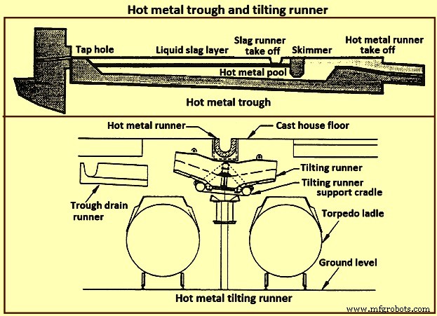
Fig 15 Hot metal trough and tilting runner
When maintenance of the trough lining is needed, the hot metal pool can be dumped by removing the hot metal dam, or by opening a trough drain gate, or by drilling into the side of the trough (at its lowest point) with a drain drill. The trough bottom is normally designed with a 2 % (minimum) slope for effective draining. Trough cross-section and length design are important for effective iron and slag flow pattern, retention, and separation. A good trough design results in hot metal yield improvements. Effective trough lining and cooling techniques are important for lining life, hot metal temperature, and cast house structural steel and concrete heat protection considerations. Troughs traditionally were contained in steel boxes ‘buried in sand’ in the cast house floor system. Improved trough design incorporates forced or natural air convection or water-cooling.
Cast house practice needs the runners to be as short as possible. This minimizes temperature loss of hot metal and reduces runner maintenance and flue generation. Shorter runners can also result in reduced capital expenditure for cast house building installation or modification. Since the runners are to slope away from the furnace, the cast house floor normally follows the same slope as the runners.
Slag runners are normally designed with a 7 % (minimum) slope. Slag can be directed to (i) slag pots for railway or mobile equipment haulage to a remote site for dumping, (ii) slag pits adjacent to the furnace for air cooling and water quenching prior to excavation by mobile equipment, and (iii) granulation facilities adjacent to the furnace for conversion of the liquid slag to granulated slag. Granulation units are provided with systems to eliminate flue emissions associated with environmental issues.
Hot metal runners are normally designed with a 3 % (minimum) slope. Hot metal is normally directed to hot metal transfer ladles (torpedo cars / open top ladles) for movement to the steel melting shop or pig casting machines. While normal practice used is to have one iron runner system with diverter gates directing the hot metal to different pouring positions, each with a ladle. Application of the tilting runner practice has been beneficial. A tilting runner is normally with an electrical motor-driven actuator (with a manual hand wheel back-up), and is tilted at around 5 degrees to divert the hot metal. A pool of hot metal is held in the tilting runner to minimize splashing and refractory wear. When one hot metal ladle has been filled, the runner is tilted to the opposite side to fill the other ladle. If needed, a locomotive removes the filled ladle and spots an empty ladle in its place. This operation can be done without plugging the furnace. When the tapping is finished, the tilting runner is tilted an additional 5 degrees to dump its pool of hot metal into the ladle.
Modern cast house design includes flat floors, where the runner is fully covered and is fitted flush with the floor. This allows safer and easier use of mobile vehicles in the cast house area. The use of radio controlled equipment and other devices have helped to reform cast house work, and these, along with effective emission control systems, have improved working conditions. As the BF hearth diameter is increased, there is a resulting need to increase the size of the cast-house. Large BF are normally designed with four tap holes (Fig 14). With a four top-hole configuration, the cast-house arrangement needs to provide sufficient space for movement around the floor itself. There is no design issues associated with this requirement as long as there is the necessary space provided in the site plan. Increasing the size of the cast-house in terms of floor plan does not represent a radical change in design philosophy which can pose a challenge the furnace designer. An efficient and strictly controlled tapping is necessary for ensuring a stable operation and high productivity of the BF.
Emission control
Fume collection requirements and applications appear to vary considerably around the globe. BFs presently have full, partial, or even no cast house fume collection system. Exhaust fan and bag house capacity of the order of 9,000 cubic meter per minute (cum/min) to 11,500 cum/min (depending upon operation and design practices) is typical for full flue capture of a two tap hole cast house installation (for trough runners and tilting runners).
Proper design and application of flue collection runner covers can facilitate cast house access (i.e. flat floor configuration using steel slabs or plates) for personnel and mobile equipment crossover. Runner covers can also reduce hot metal temperature loss and improve runner refractory longevity.
Some furnaces use flame suppression which eliminates the oxygen in the air directly over the trough and iron runners. Products of combustion prevent oxidation of the hot metal surface reducing visible particulate and flues.
Other aspects of BF design
It is necessary that complete study of every element in the process chain, from raw materials delivery to hot metal consumption is made to ensure that there are no ‘bottle necks’ in the system which can prevent the furnace from meeting the goals of its installation. While designing the BF, thought process is to be used to develop the furnace design and some alternatives are to be considered before freezing the design. During the designing of the furnace, those furnace equipments are to be selected which best meet the needs of the furnace operation.
The furnace design is to ensure (i) the furnace is capable of meeting the operational goals of production, productivity (tons per day per cubic metre of working volume), specific consumptions (kilograms per ton of hot metal), and product quality in cost effective manner, (ii) the furnace has the flexibility to accept and absorb the changes in the quality of the raw materials, and (iii) the furnace is capable of achieving the desired campaign life both with respect to time and the total production.
Financial justification is the over-riding consideration for the design. For this purpose, the economic study is to be very extensive. Further, the furnace design is to include latest technological developments so that the furnace does not become technologically outdated during its entire campaign.
The working volume of the furnace is the internal volume of the furnace calculated between the tuyeres and the stock line. Hearth productivity of the furnace is rated in tons per day per cubic metre of active hearth volume. Active hearth volume is the internal volume of the furnace calculated between the tuyeres and the tap hole. Active hearth volume is a measure of the holding capacity of the furnace for the liquids produced in the working volume (above the tuyeres). Hence, the tons per day per cubic metre of active hearth volume is a measure of the specific capacity (through-put per unit volume) of the hearth of the BF.
The design of the hearth is very important since it has a strong effect on the furnace operation. The furnace operation gets affected since the hearth liquid levels change rapidly which cause variations in gas flow pattern, gas utilization, and blast pressure. Also, because of these rapid changes in liquid level, there can be jamming / burning of the tuyeres which affect the blowing of the furnace.
The furnace hearth volume also determines the controls the operator is to exercise during furnace operation. For a very good hearth liquid level control, the high through-put furnace need around 90 % time spent in tapping. To make this time of tapping possible, cast floor is to be designed properly.
The furnace lining and cooling system needs special attention so that it does not pose any problem during the entire campaign of the BF. The selection of refractories, cooling elements, and internal furnace geometry is very important in this respect. Copper staves in this respect are expensive but they are very economical in comparison to the alternatives. Carbon lining of the hearth is very important for the long life of the hearth. The refractory lining thickness of the stack has implication on the furnace working volume.
The production needed normally determines the size of the BF. However, for the sizing of the BF, the raw materials, the product chemistry, and even operating philosophy are important. While the furnace size has implication on the capital cost, the productivity improvement has implication on the operating cost. The specific productivity of the furnace is to be determined for the determination of the size of the BF needed to produce the required quantity of hot metal. From the wide range of possible operating rates, the working volume of the furnace is to be calculated. Productivity and hence the furnace size is also to be based on the fuel rate. The fuel rate is dependent on the quality of raw materials, hot blast parameters, hot metal quality, and the operating philosophy.
The size is the most important factor for the determination of the BF productivity. However, there are other factors which also influence the BF productivity. The most important of these factors include (i) hot blast temperature and pressure, (ii) high top pressure, (iii) oxygen enrichment of the air blast, (iv) injection of auxiliary fuel at the tuyere, (v) prepared burden (sinter, pellets etc.), (vi) Fe content of the ferrous burden, (vii) ash in coke, (viii) quality of the coke, (ix) moisture content of the burden, (x) direct charging of fluxes (lime stone, dolomite etc.) in the BF, (xi) content of fines in the burden, (xii) quality of hot metal to be produced, (xiii) burden distribution control in the furnace, and (xiv) level of automation and control in the furnace.
The availability of furnace equipment, provision of stand-by equipment, and the maintenance philosophy are important factors which have high influence on the annual production from the BF. Further, incorporation of safe and healthy working practices during the operation of BF in the design of the BF is important which has a high influence on the furnace productions. In this regards, safety interlocks are to be provided at all the places where there exist a chance of unsafe operating practices to take place.
Производственный процесс
- Доменный шлак и его роль в работе печи
- Важные аспекты проектирования доменной печи и связанного с ней вспомогательного оборудования
- Система автоматизации, измерения и управления доменными процессами
- Производство и использование доменного газа
- Производительность доменной печи и влияющие параметры
- Высокоглиноземистый шлак и доменная печь
- Система охлаждения доменной печи
- Литейный дом доменной печи и его эксплуатация
- Доменная печь и ее конструкция
- Производство чугуна в доменной печи и выбросы оксида углерода