


Arduino и модуль беспроводной связи дальнего действия HC-12
<основной класс="главный сайт" id="главный">
В этом руководстве по Arduino мы узнаем, как использовать модуль беспроводной последовательной связи HC-12, который способен осуществлять беспроводную связь большого радиуса действия между несколькими платами Arduino на расстоянии до 1,8 км. Вы можете посмотреть следующее видео или прочитать письменное руководство ниже для получения более подробной информации.
Обзор
Для этого урока я сделал два основных примера, объясняющих, как подключить модуль HC-12 и установить базовую связь между двумя Arduino, и дополнительный пример, где с помощью датчика акселерометра на первом Arduino я беспроводным способом контролирую положение шагового двигателя на втором. Ардуино.
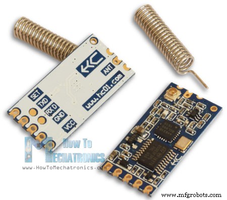
Модуль беспроводной связи HC-12
Сначала давайте более подробно рассмотрим модуль беспроводной связи последовательного порта HC-12. Вот некоторые спецификации:
- Диапазон рабочих частот беспроводной связи составляет от 433,4 МГц до 473,0 МГц.
- Всего 100 каналов с шагом 400 кГц между каждым каналом.
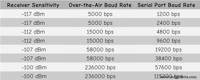
- Мощность передачи от -1 дБм (0,79 мВт) до 20 дБм (100 мВт)
- Чувствительность приема:от -117 дБм (0,019 пВт) до -100 дБм (10 пВт).
Эти значения на самом деле зависят от выбранной скорости последовательной передачи и беспроводной передачи данных, как показано в таблице.
Модуль HC-12 имеет микроконтроллер, который на самом деле не требует программирования пользователем. Для настройки модуля мы просто используем AT-команды, которые можно отправлять с Arduino, ПК или любого другого микроконтроллера, использующего последовательный порт. Для входа в режим AT-команд нам достаточно установить вывод «Set» модуля на низкий логический уровень.
Arduino и HC-12
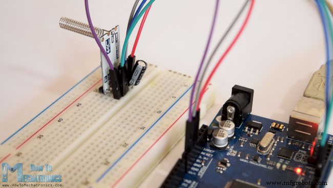
Теперь давайте подключим модуль HC-12 к Arduino и сделаем первый пример. Вот принципиальные схемы. Рабочее напряжение модуля от 3,2 В до 5,5 В и для более стабильной работы рекомендуется использовать развязывающий конденсатор и внешний источник питания. Тем не менее, я использовал USB ПК в качестве источника питания для всех трех примеров в этом руководстве, и у меня не было никаких проблем с этим.
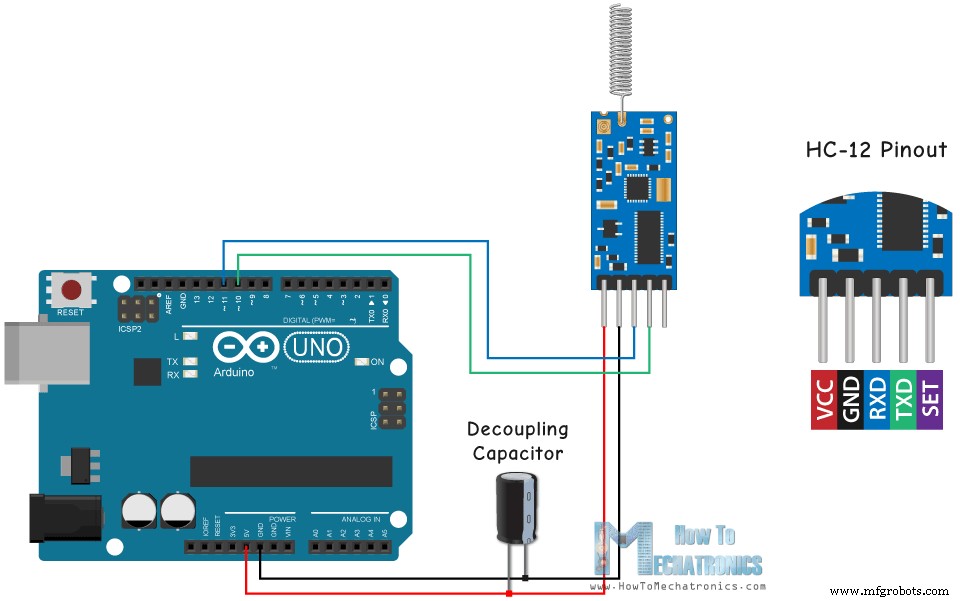
Я подключил первый модуль к Arduino UNO, а второй модуль к Arduino MEGA, но, конечно, вы можете использовать любую плату, которую захотите.
Компоненты, необходимые для этого руководства по Arduino, можно получить по ссылкам ниже:
- Модуль беспроводной связи HC-12 ………..
- Плата Arduino ………………………………………………
- Макет и соединительные провода…………………………
Пример 01 — код Arduino
Вот код Arduino для первого примера, базовая связь между двумя модулями с использованием последовательного монитора.
/* Arduino Long Range Wireless Communication using HC-12
Example 01
by Dejan Nedelkovski, www.HowToMechatronics.com
*/
#include <SoftwareSerial.h>
SoftwareSerial HC12(10, 11); // HC-12 TX Pin, HC-12 RX Pin
void setup() {
Serial.begin(9600); // Serial port to computer
HC12.begin(9600); // Serial port to HC12
}
void loop() {
while (HC12.available()) { // If HC-12 has data
Serial.write(HC12.read()); // Send the data to Serial monitor
}
while (Serial.available()) { // If Serial monitor has data
HC12.write(Serial.read()); // Send that data to HC-12
}
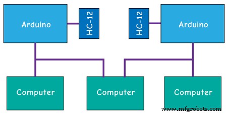
}Code language: Arduino (arduino)Один и тот же код используется для обоих Arduino. Мы можем подключить две платы Arduino к двум отдельным компьютерам, но также можем использовать один компьютер.
В этом случае, как только мы подключим первый Arduino к компьютеру, нам нужно выбрать модель и COM-порт и загрузить код в Arduino. Затем мы подключаем второй Arduino, и нам нужно снова запустить Arduino IDE, чтобы иметь возможность выбрать другой COM-порт, к которому подключен наш второй Arduino, а затем загрузить тот же код.
Итак, когда у нас запущены две среды разработки Arduino, мы можем запустить последовательные мониторы и проверить, правильно ли работает связь. Все, что мы вводим в последовательный монитор, будет отправлено с одного Arduino на другой.
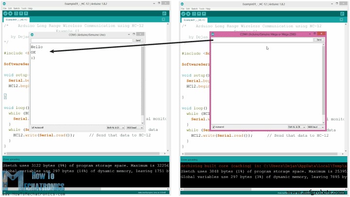
Как работает код: Итак, как только мы напечатаем что-то в мониторе последовательного порта и нажмем кнопку «Отправить», на первом Arduino цикл while с функцией Serial.available() станет истинным, и с помощью функции HC12.write() мы отправим данные из серийный монитор к модулю HC-12. Этот модуль будет передавать данные по беспроводной связи на второй модуль HC-12, поэтому на втором Arduino цикл while с функцией HC12.available() станет истинным, а с помощью функции Serial.write() данные будут отправлены на серийный монитор.
Мы можем использовать тот же код для отправки AT-команд и настройки параметров модуля. Все, что нам нужно сделать, это подключить вывод «Set» модуля к земле или любому цифровому выводу Arduino и установить на этом выводе низкий логический уровень.
Чтобы проверить, успешно ли мы вошли в режим, в последовательном мониторе мы можем ввести «AT», и мы должны получить ответное сообщение «ОК». Всего существует 12 AT-команд, и они используются для изменения различных параметров, таких как скорость передачи данных, канал, мощность передачи и т. д. Например, если мы введем «AT+B38400», скорость передачи модуля будет установлена на 38400.
AT-команды:
1. AT – тестовая команда.
Пример:отправьте «AT» модулю, и модуль вернет «ОК».
2. AT+Bxxxx – изменить скорость передачи данных последовательного порта.
Доступные скорости передачи данных:1200 бит/с, 2400 бит/с, 4800 бит/с, 9600 бит/с, 19200 бит/с, 38400 бит/с, 57600 бит/с и 115200 бит/с. По умолчанию:9600 бит/с.
Пример:Отправьте «AT+B38400» на модуль, и модуль вернет «OK+B19200».
3. AT+Cxxxx — изменить канал беспроводной связи с 001 на 100.
По умолчанию:канал 001, рабочая частота 433,4 МГц. Каждый следующий канал на 400 кГц выше.
Пример: Если мы хотим установить модуль на канал 006, нам нужно отправить модулю команду «AT+C006», и модуль вернет «OK+C006». Новая рабочая частота – 435,4 МГц.
Пример 02
Теперь давайте переместим второй пример. Здесь мы будем использовать две кнопки для выбора разных каналов связи и увидим другой способ хранения входящих данных.
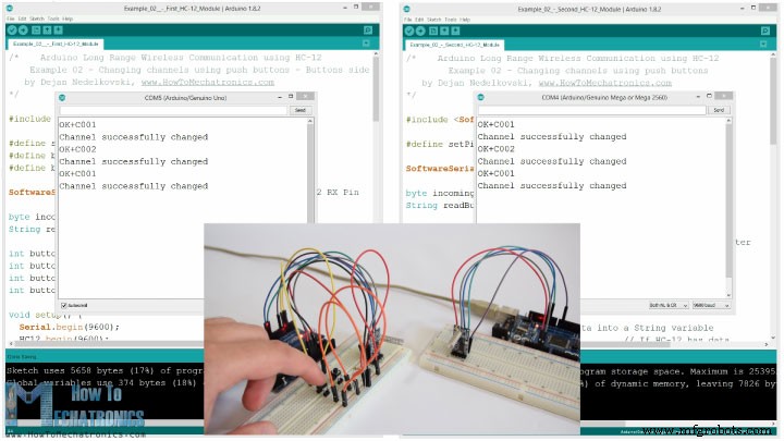
Примечание. Контакты «Set» обоих модулей HC-12 подключены к контактам номер 6 двух Arduino, а две кнопки на первом Arduino — к контактам 4 и 3.
Первый код Arduino:
/*    Arduino Long Range Wireless Communication using HC-12
    Example 02 - Changing channels using push buttons - Buttons side
   by Dejan Nedelkovski, www.HowToMechatronics.com
*/

#include <SoftwareSerial.h>

#define setPin 6
#define button1 4
#define button2 3

SoftwareSerial HC12(10, 11);         // HC-12 TX Pin, HC-12 RX Pin

byte incomingByte;
String readBuffer = "";

int button1State = 0;
int button1Pressed = 0;
int button2State = 0;
int button2Pressed = 0;

void setup() {
  Serial.begin(9600);                   // Open serial port to computer
  HC12.begin(9600);                     // Open serial port to HC12
  pinMode(setPin, OUTPUT);
  pinMode(button1, INPUT);
  pinMode(button2, INPUT);
  digitalWrite(setPin, HIGH);           // HC-12 normal, transparent mode
}

void loop() {
  // ==== Storing the incoming data into a String variable
  while (HC12.available()) {             // If HC-12 has data
    incomingByte = HC12.read();          // Store each icoming byte from HC-12
    readBuffer += char(incomingByte);    // Add each byte to ReadBuffer string variable
  }
  delay(100);
  // ==== Sending data from one HC-12 to another via the Serial Monitor
  while (Serial.available()) {
    HC12.write(Serial.read());
  }

  // ==== If button 1 is pressed, set the channel 01
  button1State = digitalRead(button1);
  if (button1State == HIGH & button1Pressed == LOW) {
    button1Pressed = HIGH;
    delay(20);
  }
  if (button1Pressed == HIGH) {
    HC12.print("AT+C001");               // Send the AT Command to the other module
    delay(100);
    //Set AT Command Mode
    digitalWrite(setPin, LOW);           // Set HC-12 into AT Command mode
    delay(100);                          // Wait for the HC-12 to enter AT Command mode
    HC12.print("AT+C001");               // Send AT Command to HC-12
    delay(200);
    while (HC12.available()) {           // If HC-12 has data (the AT Command response)
      Serial.write(HC12.read());         // Send the data to Serial monitor
    }
    Serial.println("Channel successfully changed");
    digitalWrite(setPin, HIGH);          // Exit AT Command mode
    button1Pressed = LOW;
  }

  // ====  If button 2 is pressed, set the channel 02
  button2State = digitalRead(button2);
  if (button2State == HIGH & button2Pressed == LOW) {
    button2Pressed = HIGH;
    delay(100);
  }
  if (button2Pressed == HIGH) {
    HC12.print("AT+C002"); // Send the AT Command to the other module
    delay(100);
    //Set AT Command Mode
    digitalWrite(setPin, LOW);           // Set HC-12 into AT Command mode
    delay(100);                          // Wait for the HC-12 to enter AT Command mode
    HC12.print("AT+C002");               // Send AT Command to HC-12
    delay(200);
    while (HC12.available()) {           // If HC-12 has data (the AT Command response)
      Serial.write(HC12.read());         // Send the data to Serial monitor
    }
    Serial.println("Channel successfully changed");
    digitalWrite(setPin, HIGH);
    button2Pressed = LOW;
  }
  checkATCommand();
  readBuffer = "";                       // Clear readBuffer
}
// ==== Custom function - Check whether we have received an AT Command via the Serial Monitor
void checkATCommand () {
  if (readBuffer.startsWith("AT")) {     // Check whether the String starts with "AT"
    digitalWrite(setPin, LOW);           // Set HC-12 into AT Command mode
    delay(200);                          // Wait for the HC-12 to enter AT Command mode
    HC12.print(readBuffer);              // Send AT Command to HC-12
    delay(200);
    while (HC12.available()) {           // If HC-12 has data (the AT Command response)
      Serial.write(HC12.read());         // Send the data to Serial monitor
    }
    digitalWrite(setPin, HIGH);          // Exit AT Command mode
  }
}Code language: Arduino (arduino)
Второй код Arduino:
/*    Arduino Long Range Wireless Communication using HC-12
        Example 02 - Changing channels using push buttons
   by Dejan Nedelkovski, www.HowToMechatronics.com
*/

#include <SoftwareSerial.h>

#define setPin 6

SoftwareSerial HC12(10, 11); // HC-12 TX Pin, HC-12 RX Pin

byte incomingByte;
String readBuffer = "";

void setup() {
  Serial.begin(9600);             // Open serial port to computer
  HC12.begin(9600);               // Open serial port to HC12
  pinMode(setPin, OUTPUT);
  digitalWrite(setPin, HIGH);     // HC-12 normal mode
}

void loop() {
  // ==== Storing the incoming data into a String variable
  while (HC12.available()) {             // If HC-12 has data
    incomingByte = HC12.read();          // Store each icoming byte from HC-12
    readBuffer += char(incomingByte);    // Add each byte to ReadBuffer string variable
  }
  delay(100);
  // ==== Sending data from one HC-12 to another via the Serial Monitor
  while (Serial.available()) {
    HC12.write(Serial.read());
  }
  // === If button 1 is pressed, set channel 01
  if (readBuffer == "AT+C001") {
    digitalWrite(setPin, LOW);           // Set HC-12 into AT Command mode
    delay(100);                          // Wait for the HC-12 to enter AT Command mode
    HC12.print(readBuffer);              // Send AT Command to HC-12 ("AT+C001")
    delay(200);
    while (HC12.available()) {           // If HC-12 has data (the AT Command response)
      Serial.write(HC12.read());         // Send the data to Serial monitor
    }
    Serial.println("Channel successfully changed");
    digitalWrite(setPin, HIGH);          // Exit AT Command mode
    readBuffer = "";
  }
  // === If button 2 is pressed, set channel 02
  if (readBuffer == "AT+C002") {
    digitalWrite(setPin, LOW);           // Set HC-12 into AT Command mode
    delay(100);                          // Wait for the HC-12 to enter AT Command mode
    HC12.print(readBuffer);              // Send AT Command to HC-12
    delay(200);
    while (HC12.available()) {           // If HC-12 has data (the AT Command response)
      Serial.write(HC12.read());         // Send the data to Serial monitor
    }
    Serial.println("Channel successfully changed");
    digitalWrite(setPin, HIGH);          // Exit AT Command mode

    readBuffer = "";
  }
  checkATCommand();
  readBuffer = "";                       // Clear readBuffer
}
// ==== Custom function - Check whether we have received an AT Command via the Serial Monitor
void checkATCommand () {
  if (readBuffer.startsWith("AT")) {     // Check whether the String starts with "AT"
    digitalWrite(setPin, LOW);           // Set HC-12 into AT Command mode
    delay(100);                          // Wait for the HC-12 to enter AT Command mode
    HC12.print(readBuffer);              // Send AT Command to HC-12
    delay(200);
    while (HC12.available()) {           // If HC-12 has data (the AT Command response)
      Serial.write(HC12.read());         // Send the data to Serial monitor
    }
    digitalWrite(setPin, HIGH);          // Exit AT Command mode
  }
}Code language: Arduino (arduino)
Описание кодов:
Итак, сначала нам нужно определить выводы и установить вывод «Set» на высокий логический уровень, чтобы модуль работал в обычном, прозрачном режиме. В первом цикле while мы сохраняем входящие данные в строковую переменную, чтобы лучше с ними обращаться.
// ==== Storing the incoming data into a String variable
while (HC12.available()) { // If HC-12 has data
incomingByte = HC12.read(); // Store each icoming byte from HC-12
readBuffer += char(incomingByte); // Add each byte to ReadBuffer string variable
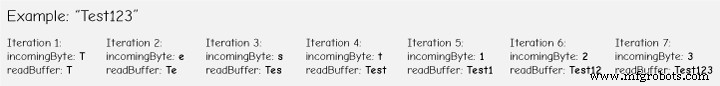
}Code language: Arduino (arduino)Входящие данные всегда приходят по одному байту за раз, поэтому, например, если мы отправим строку «Test123» со второго Arduino, этот цикл while выполнит 7 итераций. На каждой итерации с помощью функции HC12.read() мы будем считывать каждый входящий байт или символ и добавлять его в переменную String с именем «readBuffer».
Далее давайте посмотрим, как мы можем изменить канал связи, используя первую кнопку. Поэтому, если мы нажмем первую кнопку, с помощью функции HC12.print() мы отправим строку «AT+C001» на модуль HC-12 или на второй Arduino.
if (button1Pressed == HIGH) {
    HC12.print("AT+C001");               // Send the AT Command to the other module
    delay(100);
    //Set AT Command Mode
    digitalWrite(setPin, LOW);           // Set HC-12 into AT Command mode
    delay(100);                          // Wait for the HC-12 to enter AT Command mode
    HC12.print("AT+C001");               // Send AT Command to HC-12
    delay(200);
    while (HC12.available()) {           // If HC-12 has data (the AT Command response)
      Serial.write(HC12.read());         // Send the data to Serial monitor
    }
    Serial.println("Channel successfully changed");
    digitalWrite(setPin, HIGH);          // Exit AT Command mode
    button1Pressed = LOW;
  }Code language: Arduino (arduino)
Когда эта строка будет получена на втором Arduino, мы установим модуль HC-12 в режим AT-команд, а затем напишем в него ту же строку «AT+C001», которая установит модуль на канал связи номер один.
// At the second Arduino

// === If button 1 is pressed, set channel 01
  if (readBuffer == "AT+C001") {
    digitalWrite(setPin, LOW);           // Set HC-12 into AT Command mode
    delay(100);                          // Wait for the HC-12 to enter AT Command mode
    HC12.print(readBuffer);              // Send AT Command to HC-12 ("AT+C001")
    delay(200);
    while (HC12.available()) {           // If HC-12 has data (the AT Command response)
      Serial.write(HC12.read());         // Send the data to Serial monitor
    }
    Serial.println("Channel successfully changed");
    digitalWrite(setPin, HIGH);          // Exit AT Command mode
    readBuffer = "";
  }Code language: Arduino (arduino)
Мы используем следующий цикл while для вывода ответного сообщения от модуля HC-12 о том, успешно ли изменен канал.
while (HC12.available()) {           // If HC-12 has data (the AT Command response)
      Serial.write(HC12.read());         // Send the data to Serial monitor
    }Code language: Arduino (arduino)
Вернувшись к первому Arduino, мы выполняем ту же процедуру отправки AT-команды на первый модуль HC-12. Таким же образом мы, нажатием второй кнопки, устанавливаем канал связи номер два. Таким образом, используя этот метод, мы можем в любое время выбрать, с каким модулем HC-12 мы будем обмениваться данными.
В конце пользовательская функция checkATCommand() проверяет, является ли полученное сообщение AT-командой, проверяя, начинается ли строка с «AT». Если это так, модуль переходит в режим AT-команд и выполняет команду.
// ==== Custom function - Check whether we have received an AT Command via the Serial Monitor
void checkATCommand () {
  if (readBuffer.startsWith("AT")) {     // Check whether the String starts with "AT"
    digitalWrite(setPin, LOW);           // Set HC-12 into AT Command mode
    delay(200);                          // Wait for the HC-12 to enter AT Command mode
    HC12.print(readBuffer);              // Send AT Command to HC-12
    delay(200);
    while (HC12.available()) {           // If HC-12 has data (the AT Command response)
      Serial.write(HC12.read());         // Send the data to Serial monitor
    }
    digitalWrite(setPin, HIGH);          // Exit AT Command mode
  }
}Code language: Arduino (arduino)
Беспроводная связь HC-12:управление шаговым двигателем с помощью акселерометра
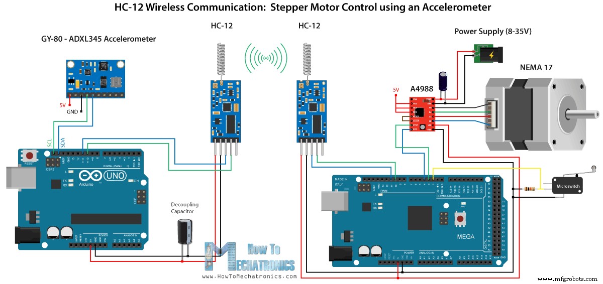
Теперь давайте посмотрим на третий пример. Здесь мы контролируем положение шагового двигателя на втором Arduino, используя модуль акселерометра на первом Arduino.
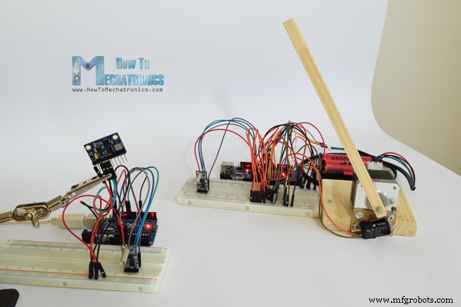
Схема также содержит микропереключатель для нахождения начального положения шагового двигателя в 0 градусов.
Компоненты, необходимые для этого примера, можно получить по ссылкам ниже:
- Модуль беспроводной связи HC-12 …………
- Драйвер шагового двигателя A4988 …………………………..
- Шаговый двигатель NEMA 17 …………………………………
- Плата Arduino ………………………………………………..
- Макет и соединительные провода ……………………………..
- Плата GY-80 с акселерометром ADXL345………
Обратите внимание, что у меня уже есть подробные руководства по подключению и использованию как акселерометра, так и шагового двигателя, поэтому в этом примере я объясню только часть кода HC-12.
Первый Arduino — код передатчика:
/*   Arduino Long Range Wireless Communication using HC-12
     Example 03 - Stepper Motor Control using Accelerometer - Transmitter, Accelerometer
    by Dejan Nedelkovski, www.HowToMechatronics.com
*/

#include <SoftwareSerial.h>
#include <Wire.h>

SoftwareSerial HC12(10, 11); // HC-12 TX Pin, HC-12 RX Pin

float angle;
int lastAngle = 0;
int count = 0;
int angleSum = 0;

//--- Accelerometer Register Addresses
#define Power_Register 0x2D
#define X_Axis_Register_DATAX0 0x32 // Hexadecima address for the DATAX0 internal register.
#define X_Axis_Register_DATAX1 0x33 // Hexadecima address for the DATAX1 internal register.
#define Y_Axis_Register_DATAY0 0x34
#define Y_Axis_Register_DATAY1 0x35
#define Z_Axis_Register_DATAZ0 0x36
#define Z_Axis_Register_DATAZ1 0x37
int ADXAddress = 0x53;  //Device address in which is also included the 8th bit for selecting the mode, read in this case.
int X0, X1, X_out;
int Y0, Y1, Y_out;
int Z1, Z0, Z_out;
float Xa, Ya, Za;

void setup() {
  HC12.begin(9600);               // Open serial port to HC12
  Wire.begin(); // Initiate the Wire library
  Serial.begin(9600);
  delay(100);

  Wire.beginTransmission(ADXAddress);
  Wire.write(Power_Register); // Power_CTL Register
  // Enable measurement
  Wire.write(8); // Bit D3 High for measuring enable (0000 1000)
  Wire.endTransmission();
}
void loop() {
  // X-axis
  Wire.beginTransmission(ADXAddress); // Begin transmission to the Sensor
  //Ask the particular registers for data
  Wire.write(X_Axis_Register_DATAX0);
  Wire.write(X_Axis_Register_DATAX1);
  Wire.endTransmission(); // Ends the transmission and transmits the data from the two registers
  Wire.requestFrom(ADXAddress, 2); // Request the transmitted two bytes from the two registers
  if (Wire.available() <= 2) { //
    X0 = Wire.read(); // Reads the data from the register
    X1 = Wire.read();
    /* Converting the raw data of the X-Axis into X-Axis Acceleration
      - The output data is Two's complement
      - X0 as the least significant byte
      - X1 as the most significant byte */
    X1 = X1 << 8;
    X_out = X0 + X1;
    Xa = X_out / 256.0; // Xa = output value from -1 to +1, Gravity acceleration acting on the X-Axis
  }
  //Serial.print("Xa= ");
  //Serial.println(X_out);

  // Y-Axis
  Wire.beginTransmission(ADXAddress);
  Wire.write(Y_Axis_Register_DATAY0);
  Wire.write(Y_Axis_Register_DATAY1);
  Wire.endTransmission();
  Wire.requestFrom(ADXAddress, 2);
  if (Wire.available() <= 2) {
    Y0 = Wire.read();
    Y1 = Wire.read();
    Y1 = Y1 << 8;
    Y_out = Y0 + Y1;
    Ya = Y_out / 256.0;
  }

  // Combine X and Y values for getting the angle value from 0 to 180 degrees
  if (Y_out > 0) {
    angle = map(Y_out, 0, 256, 90, 0);
  }
  else if (Y_out < 0) {
    angle = map(Y_out, 256, 0, 90, 0);
    angle = 90 - angle;
  }
  if (X_out < 0 & Y_out < 0) {
    angle = 180;
  }
  if (X_out < 0 & Y_out >0) {
    angle = 0;
  }

  // float to int
  int angleInt = int(angle);
  // Makes 100 accelerometer readings and sends the average for smoother result
  angleSum = angleSum + angleInt;
  count++;
  if (count >= 100) {
    angleInt = angleSum / 100;
    angleSum = 0;
    count = 0;
    // Some more smoothing of acceleromter reading - sends the new angle only if it differes from the previous one by +-2
    if (angleInt > lastAngle + 2 || angleInt < lastAngle - 2) {
      Serial.println(angleInt);
      String angleString = String(angleInt);
      //sends the angle value with start marker "s" and end marker "e"
      HC12.print("s" + angleString + "e");
      delay(10);
      lastAngle = angleInt;
      angleSum = 0;
      count = 0;
    }
  }
}
Code language: Arduino (arduino)
Второй Arduino — код приемника:
/*   Arduino Long Range Wireless Communication using HC-12
     Example 03 - Stepper Motor Control using Accelerometer - Receiver, Stepper Motor

    by Dejan Nedelkovski, www.HowToMechatronics.com
*/
#include <SoftwareSerial.h>

SoftwareSerial HC12(10, 11); // HC-12 TX Pin, HC-12 RX Pin

char incomingByte;
String readBuffer = "";

// defines pins numbers
const int dirPin = 4;
const int stepPin = 3;
const int button = 2;

int currentAngle = 0;
int lastAngle = 0;
int rotate = 0;

void setup() {
  Serial.begin(9600);             // Open serial port to computer
  HC12.begin(9600);               // Open serial port to HC12

  // Sets the two pins as Outputs
  pinMode(dirPin, OUTPUT);
  pinMode(stepPin, OUTPUT);
  // Microswitch input, with internal pull-up resistor activated
  pinMode(button, INPUT_PULLUP);
  delay(10);
  digitalWrite(dirPin, HIGH);
  boolean startingPosition = true;
  while (startingPosition) {
    digitalWrite(stepPin, HIGH);
    delayMicroseconds(200);
    digitalWrite(stepPin, LOW);
    delayMicroseconds(200);
    if (digitalRead(button) == LOW) {
      startingPosition = false;
    }
  }
  delay(100);
}
void loop() {
  readBuffer = "";
  boolean start = false;
  // Reads the incoming angle
  while (HC12.available()) {             // If HC-12 has data
    incomingByte = HC12.read();          // Store each icoming byte from HC-12
    delay(5);
    // Reads the data between the start "s" and end marker "e"
    if (start == true) {
      if (incomingByte != 'e') {
        readBuffer += char(incomingByte);    // Add each byte to ReadBuffer string variable
      }
      else {
        start = false;
      }
    }
    // Checks whether the received message statrs with the start marker "s"
    else if ( incomingByte == 's') {
      start = true; // If true start reading the message
    }
  }
  // Converts the string into integer
  currentAngle = readBuffer.toInt();
  // Makes sure it uses angles between 0 and 180
  if (currentAngle > 0 && currentAngle < 180) {
    // Convert angle value to steps (depending on the selected step resolution)
    // A cycle = 200 steps, 180deg = 100 steps ; Resolution: Sixteenth step x16
    currentAngle = map(currentAngle, 0, 180, 0, 1600);
    //Serial.println(currentAngle); // Prints the angle on the serial monitor
    digitalWrite(dirPin, LOW); // Enables the motor to move in a particular direction
    // Rotates the motor the amount of steps that differs from the previous positon
    if (currentAngle != lastAngle) {
      if (currentAngle > lastAngle) {
        rotate = currentAngle - lastAngle;
        for (int x = 0; x < rotate; x++) {
          digitalWrite(stepPin, HIGH);
          delayMicroseconds(400);
          digitalWrite(stepPin, LOW);
          delayMicroseconds(400);
        }
      }
      // rotate the other way
      if (currentAngle < lastAngle) {
        rotate = lastAngle - currentAngle;
        digitalWrite(dirPin, HIGH);        //Changes the rotations direction
        for (int x = 0; x < rotate; x++) {
          digitalWrite(stepPin, HIGH);
          delayMicroseconds(400);
          digitalWrite(stepPin, LOW);
          delayMicroseconds(400);
        }
      }
    }
    lastAngle = currentAngle;  // Remembers the current/ last positon
  }
}Code language: Arduino (arduino)
Описание кодов:
Итак, сначала мы определяем контакты и инициализируем модули в разделе настройки. Затем мы считываем значения осей X и Y акселерометра и сопоставляем их со значениями от 0 до 180 градусов. Значения, поступающие с акселерометра, иногда могут быть нестабильными или трястись, поэтому для сглаживания результата я использовал среднее значение из ста показаний.
// Makes 100 accelerometer readings and sends the average for smoother result
  angleSum = angleSum + angleInt;
  count++;
  if (count >= 100) {
    angleInt = angleSum / 100;
    angleSum = 0;
    count = 0;
    // Some more smoothing of acceleromter reading - sends the new angle only if it differes from the previous one by +-2
    if (angleInt > lastAngle + 2 || angleInt < lastAngle - 2) {
      Serial.println(angleInt);
      String angleString = String(angleInt);
      //sends the angle value with start marker "s" and end marker "e"
      HC12.print("s" + angleString + "e");
      delay(10);
      lastAngle = angleInt;
      angleSum = 0;
      count = 0;
    }
  }Code language: Arduino (arduino)
Для еще большего сглаживания я буду присылать новое значение угла только в том случае, если оно отличается от предыдущего на 2.
Здесь обратите внимание, что при отправке угла в модуль HC-12 я также отправляю символ «s» впереди, а символ «e» после, что поможет мне при получении данных на втором Arduino.
На втором Ардуино ждем, пока не придет маркер начала «s», затем считываем значение угла, пока не придет маркер конца «e». Таким образом мы уверены, что получим только значение угла.
// Reads the incoming angle
  while (HC12.available()) {             // If HC-12 has data
    incomingByte = HC12.read();          // Store each icoming byte from HC-12
    delay(5);
    // Reads the data between the start "s" and end marker "e"
    if (start == true) {
      if (incomingByte != 'e') {
        readBuffer += char(incomingByte);    // Add each byte to ReadBuffer string variable
      }
      else {
        start = false;
      }
    }
    // Checks whether the received message statrs with the start marker "s"
    else if ( incomingByte == 's') {
      start = true; // If true start reading the message
    }
  }Code language: Arduino (arduino)
Затем мы конвертируем значение в целое число и сопоставляем значение от 0 до 1600 шагов, что соответствует выбранному разрешению шестнадцатого шага в драйвере шагового двигателя A4988. Затем мы поворачиваем шаговый двигатель на текущий угол.
Вот и все для этого урока по Arduino. Не стесняйтесь задавать любые вопросы в разделе комментариев ниже.
Производственный процесс
- Диапазон беспроводной связи
- Почему беспроводная связь большого радиуса действия с питанием от батареи разрушительна
- ЖК-анимация и игры
- Генератор волн JX
- u-blox LEA-6H 02 GPS-модуль с Arduino и Python
- Беспроводной ИК-сканер температуры
- Связь Python3 и Arduino
- FM-радио с использованием Arduino и RDA8057M
- Система обнаружения падений на базе Arduino, Windows и Azure
- Будильник ArduRadio