


Технологии и системы очистки дымовых газов
Технологии и системы очистки дымовых газов
Загрязнение окружающей среды является одной из самых больших проблем во всем мире в настоящее время. Из ряда глобальных экологических проблем все больше и больше людей осознали, что окружающая среда и ресурсы являются основными потребностями для выживания и развития человека. Дымовые газы, являющиеся продуктом большинства технологических процессов, загрязнены разнообразными твердыми частицами. Чтобы в дальнейшем использовать газы (если они имеют достаточную теплотворную способность) или выпустить их в атмосферу, необходимо очистить газы. Однако контроль за выбросами в атмосферу стоит денег и редко приносит финансовую отдачу эксплуатирующей организации.
За последние несколько лет произошли полные изменения в подходах, образовании, ответственности и правилах в области контроля выбросов в различных странах. Правила контроля выбросов с течением времени ужесточаются в попытке уберечь будущие поколения от пагубных последствий загрязнения атмосферы. В настоящее время несколько организаций быстро меняют свое отношение к загрязнению атмосферы и активно участвуют в мероприятиях по борьбе с загрязнением. Теперь организации хотят, чтобы общественность воспринимала их как ответственные организации, производящие «чистую» продукцию. Отчасти это обусловлено рынком, поскольку сейчас рынки требуют все больше и больше «чистых» продуктов. Клиенты в сегодняшней ситуации становятся более образованными как в отношении своей ответственности по отношению к окружающей среде, так и в отношении преимуществ чистой окружающей среды.
Целью системы очистки дымовых газов является снижение выбросов в атмосферу веществ, опасных для окружающей среды и здоровья человека. Это включает, например. тяжелые металлы, диоксины и вещества, вызывающие подкисление и эвтрофикацию. Поскольку некоторые вещества в дымовых газах являются токсичными и канцерогенными, важно уменьшить их выбросы. Закисление лесов и озер было существенно снижено за счет удаления оксидов серы и азота из дымовых газов.
В технологических процессах металлургических, химических и тепловых электростанций образуются отходящие дымовые газы, обычно запыленные и имеющие высокие температуры. Состав и количество этих газов зависят от характера технологических процессов и сырья. Выбросы отработанных дымовых газов на самом деле являются результатом используемого сырья, а также процессов и реакций, происходящих на этих установках. Дымовые газы могут содержать диоксид углерода, оксид углерода, оксиды серы (SO2 и SO3) и азота (NOx), водород, сероводород (H2S), фтор (в виде HF), хлор (в виде HCl ), мышьяк, ртуть, летучие органические соединения (ЛОС), водяной пар, пыль и т. д. Водяной пар безвреден, но способствует образованию видимого шлейфа на выходе из дымовой трубы.
Существует несколько технологических процессов, протекающих при высоких температурах. Кроме того, многие из этих процессов обрабатывают сырье, некоторые из них находятся в форме мелких частиц. Следовательно, все эти процессы склонны к выбросу загрязняющих газов и твердых частиц в атмосферу. Это, в свою очередь, влияет на качество воздуха вокруг растения. Чтобы улучшить и защитить качество воздуха, для сокращения выбросов используются различные устройства контроля загрязнения. Раньше в течение многих лет оборудование для контроля загрязнения использовалось только для тех процессов, где количество загрязняющих веществ было очень высоким или они были токсичными по своей природе. Это оборудование также ранее использовалось там, где оно имело некоторую восстановительную ценность. Но в нынешнем сценарии, когда экологические нормы становятся все более и более жесткими, а общество все больше беспокоится об окружающей среде, необходимо изучить выбросы всех технологических процессов и установить оборудование во всех областях, чтобы уменьшить выбросы до минимально возможных уровней.
Существует по крайней мере пять основных групп источников загрязнения атмосферы, обычно связанных с технологическими процессами, каждая из которых имеет конкретные передовые технологии борьбы с загрязнением. Эти группы не составляют исчерпывающего списка, поскольку там, где встречаются сильные концентрации кислых газов; должны быть реализованы альтернативные технологии очистки дымовых газов, такие как заводы по производству серной кислоты. Эти пять основных групп технологий газоочистки связаны с (i) контролем выбросов пыли и твердых частиц, (ii) контролем кислых газов, таких как SO2 / HCl и HF, (iii) контролем выбросов NOx, (iv) кислотным туманом и другими аэрозолями. контроль и (v) контроль ртути, диоксинов/фуранов и летучих органических соединений. Для технологий фиксации кислых газов утилизация продуктов, как всегда, остается сложной задачей. В большинстве случаев отходы просто выбрасываются на свалку, что сопряжено с необходимыми эксплуатационными расходами. Оборудование для контроля выбросов для этих пяти групп технологий газоочистки в основном относится к двум типам (i) оборудование для контроля за выбросами пыли и твердых частиц и (ii) оборудование для контроля за выбросами газообразных веществ. В этой статье основное внимание уделяется системам контроля выбросов пыли и твердых частиц.
Проблема очистки высокотемпературных газов вообще является, пожалуй, самой сложной для промышленности. Это сложно, так как проблема обычно связана с чрезвычайно мелкими частицами, диспергированными в газах при температурах, которые могут варьироваться от 700°C до 1500°C. В некоторых случаях могут иметь место даже более высокие температуры. Из-за мелкодисперсного аэрозоля и высоких температур обычные подходы обычно не решают проблему. Поэтому прогресс в этой области был не таким стремительным. Основные проблемы, связанные с высокотемпературной очисткой газов, связаны с экономикой и основными требованиями к очистке.
В некоторых случаях необходима очистка отходящих газов, поскольку они представляют собой материал, представляющий значительную ценность, или, если материал в виде частиц удаляется, остается горючий газ, который рекуперируется в виде тепла или энергии, которые можно использовать в промышленности. процесс. В других случаях экономическая ценность сточных вод, будь то твердые частицы, газообразные или их обычная комбинация, настолько мала, что стоимость удаления представляет собой серьезную проблему. В этих случаях очистка или удаление, необходимые для предотвращения загрязнения воздуха, приносят только нематериальную отдачу.
Во второй категории желание отрасли состоит в том, чтобы получить очистку с минимальными затратами, не налагая бремени в виде увеличения производственных затрат. Затраты на предотвращение загрязнения воздуха в населенных пунктах и возможного ущерба имуществу или населению, как правило, не окупаются ничем, кроме хороших отношений с общественностью.
Эффективная очистка этих газов представляет серьезные технические проблемы из-за большого количества примесей. Высокоэффективные системы газоочистки жизненно важны для надежной работы и длительного срока службы высокотемпературных металлургических и тепловых электростанций и позволяют операторам соблюдать соответствующие стандарты контроля загрязнения. Выбор установок для охлаждения и очистки газа имеет решающее значение с точки зрения технической осуществимости, экономической приемлемости и совместимости с окружающей средой. Кроме того, системы газоочистки должны быть разработаны с учетом высочайшего уровня эффективности очистки, безопасности и надежности, обеспечивая при этом наилучшую возможную защиту окружающей среды.
Важными критериями для проектирования системы газоочистки являются (i) объем газа в N м3 в час, (ii) химический состав газов, (iii) влажность газов, (iv) температура газов, (v ) содержание пыли в газах в кг в час, (vi) характеристики пыли, такие как коррозионная, абразивная и т. д., (vii) диапазон размеров частиц пыли, (viii) стандарты выбросов, (ix) взрывоопасность газа , (x) гигиеничный дизайн, (xi) системы, подключенные к сети или в автономном режиме, и (xii) материалы конструкции.
При проектировании системы газоочистки необходимо учитывать три основных момента. Во-первых, это колпак, который должен улавливать выделяемые пыль и газы и предотвращать задымление рабочей зоны. Во-вторых, газ и пыль, улавливаемые вытяжкой, перед выпуском в атмосферу подлежат очистке. В-третьих, собранная пыль должна быть утилизирована таким образом, чтобы она не попадала в воздух или реку, чтобы снова не стать проблемой загрязнения.
Дымовые газы, поступающие из металлургических печей, часто имеют высокие температуры (от 700°С до 1500°С и даже выше) и высокую запыленность. Следовательно, перед обработкой этих газов в системе газоочистки эти газы необходимо охладить до температуры ниже 400 град С. На практике применяют несколько способов охлаждения газов. Это (i) котел-утилизатор, (ii) косвенное охлаждение воздухом, (iii) косвенное охлаждение водой и (iv) испарительное охлаждение водой.
Котлы-утилизаторы в основном используются для охлаждения дымовых газов тех технологических процессов, которые производят дымовые газы с непрерывным расходом газа. Это позволяет применять охлаждение газа с помощью котла-утилизатора с хорошими эксплуатационными результатами.
Система охлаждения газов косвенным охлаждением воздухом на практике применяется относительно редко из-за ряда недостатков, таких как (i) охлаждающий воздух имеет более низкую температуру, чем точка росы технологического газа, а конденсация кислоты происходит на охлаждающих стенок, что вызывает коррозию оборудования, (ii) риск налипания и закупорки из-за липкой пыли, (iii) длительное время пребывания газа при высокой температуре (выше 550°C), что вызывает дополнительное образование SO3 и повышает точку росы газа, и (iv) в случае колебания расхода газа трудно контролировать температуру газа на выходе.
Часто используется система охлаждения газов косвенным охлаждением водой. В этом случае дымоход имеет по окружности водяные трубы, по которым течет охлаждающая вода. Размеры труб и параметры воды (напор и расход) должны быть такими, чтобы температура нагретой воды всегда оставалась ниже уровней ее испарения. В то время как система позволяет избежать использования пара и нормативных требований, связанных с обработкой пара, недостаток системы связан с более громоздким оборудованием и обработкой большего объема охлаждающей воды.
Испарительное охлаждение водой является подходящей технической альтернативой косвенному воздушному охлаждению или котлам-утилизаторам для охлаждения газов с колеблющимся расходом газа. Современное оборудование для испарительного охлаждения использует специальный вид распылительных форсунок, так называемые двухкомпонентные форсунки (вода и сжатый воздух), которые позволяют гибко работать и точно контролировать температуру газа на выходе из охладителя. Эта особенность очень важна для предотвращения чрезмерного падения температуры газа, которое может вызвать конденсацию кислотного тумана и, как следствие, смачивание пыли и образование отложений влажной пыли в последующих осадителях горячих газов, а также коррозию. Преимущества использования испарительных охладителей:(i) испарительное охлаждение снижает образование дополнительного количества SO3 в газе из-за короткого времени пребывания газа перед испарительным охладителем при высокой температуре (выше 550°С) в присутствии твердых соединений металлов. которые действуют как катализаторы. (ii) ниже по потоку от испарительного охладителя образование SO3 подавляется, (iii) кондиционирование газа водой для улучшения работы электрофильтра (ESP) и (iv) не требуются внутренние устройства, такие как направляющие лопатки.
На сегодняшний день доступно около 40 различных типов газоочистных устройств, и, исходя из общих характеристик, их можно разделить на пять основных типов, а именно (i) туманоуловители, (ii) пылеуловители (также иногда называемые пылеуловителями) и циклоны, (iii) мокрые пылеуловители, (iv) фильтры и (v) ЭСП. Кроме того, системы газоочистки могут быть основаны на технологиях сухого пылеотделения или технологиях мокрого пылеотделения. В технологиях сухого пылеудаления может потребоваться кондиционирование газа водой исходя из требований технологического процесса. Кондиционирование газа осуществляется путем подачи воды вместе с азотом в колонну кондиционирования для получения водяного тумана с каплями диаметром около 150 микрометров. Время пребывания газа в колонне регулируется таким образом, чтобы все капли полностью испарялись на выходе из колонны кондиционирования.
Устройства для удаления твердых частиц работают в основном на том принципе, что газовый поток, содержащий частицы, проходит через область, где на частицы воздействуют внешние силы или они заставляют перехватывать препятствия, тем самым отделяя их от газового потока. Под действием внешних сил частицы приобретают составляющую скорости в направлении, отличном от направления потока газа. Чтобы спроектировать сепарационное устройство, основанное на разделении частиц внешними силами, необходимо рассчитать движение частицы в таких условиях.
Предварительный выбор подходящих систем контроля выбросов твердых частиц обычно основывается на знании четырех аспектов, а именно (i) концентрации твердых частиц в очищаемом потоке, (ii) распределении частиц по размерам, которые необходимо удалить, (iii) газовом потоке. уровень, и (iv) окончательный допустимый уровень выбросов твердых частиц. После выбора систем, способных обеспечить требуемую эффективность при данных скоростях потока, окончательный выбор обычно делается на основе общей стоимости строительства и эксплуатации. Размер коллектора, а значит, и его стоимость, прямо пропорциональны объемному расходу очищаемого газа. Эксплуатационные факторы, влияющие на стоимость устройства, — это перепад давления в устройстве, требуемая мощность и необходимое количество воды (в случае системы мокрой очистки). Устройства, удаляющие частицы из газовых потоков, основаны на одном или нескольких из следующих физических механизмов.
Седиментация – Газовый поток, содержащий частицы, вводят в устройство или камеру, где частицы оседают под действием силы тяжести на дно камеры. Устройства такого типа называются отстойниками.
Миграция заряженных частиц в электрическом поле – Газовый поток, содержащий частицы, вводят в устройство, в котором частицы заряжаются, а затем подвергаются воздействию электрического поля. Возникающая в результате электростатическая сила, действующая на частицы, заставляет их мигрировать к одной из поверхностей устройства, где они удерживаются и собираются. Устройства этого типа называются ESP.
Инерционное осаждение – Когда поток газа меняет направление, обтекая объект на своем пути, взвешенные частицы имеют тенденцию продолжать двигаться в первоначальном направлении из-за своей инерции. К устройствам для сбора твердых частиц, основанным на этом принципе, относятся циклоны, скрубберы и фильтры.
Брауновская диффузия – Взвешенные в газе частицы всегда находятся в броуновском движении. Броуновское движение – это хаотическое движение взвешенных в среде частиц. Этот образец движения обычно состоит из случайных колебаний положения частицы внутри подобласти жидкости, за которыми следует перемещение в другую подобласть. Когда газовый поток обтекает препятствия, естественное беспорядочное движение частиц приводит их в соприкосновение с препятствиями, где они прилипают и собираются. Поскольку броуновское движение более выражено для более мелких частиц, ожидается, что устройства, основанные на диффузии как механизме разделения, наиболее эффективны для мелких частиц.
Ключевым параметром, влияющим на выбор устройства, которое следует использовать в конкретном случае, является диаметр частиц Dp. Физические механизмы, указанные выше, сильно различаются по своей эффективности в зависимости от размера частицы. Таким образом, эффективность устройств для удаления твердых частиц зависит от размера частиц.
Эффективность улавливания N(Dp) газоочистным устройством частиц диаметром Dp определяется уравнением N(Dp) =1- (количество частиц диаметром Dp на куб. частиц диаметром Dp на кубометр газа в). Общая эффективность «N» устройства, основанная на количестве частиц, определяется уравнением N =1 – (количество частиц на кубический сантиметр выходящего газа) / (количество частиц на кубический сантиметр входящего газа). Эти показатели эффективности могут быть выражены в терминах функций распределения частиц по размерам на входе и выходе устройства.
Существует несколько различных классов оборудования для контроля твердых частиц. Простейшим устройством для контроля твердых частиц является отстойная камера, большая камера, в которой скорость газа замедляется, что позволяет частицам оседать под действием силы тяжести. Циклон работает, заставляя весь газовый поток течь по спирали внутри конической трубы. Под действием центробежной силы частицы мигрируют наружу и собираются на стенках пробирки. Частицы соскальзывают со стенки и падают на дно, откуда удаляются. Чистый газ обычно меняет направление потока и выходит из верхней части циклона.
ESP использует электростатическую силу, воздействующую на заряженные частицы в электрическом поле, для отделения частиц от газового потока. Между двумя электродами устанавливается высокое падение напряжения, и частицы, проходя через возникающее электрическое поле, приобретают заряд. Заряженные частицы мигрируют и собираются на противоположно заряженной пластине, в то время как чистый газ проходит через устройство. Периодически пластины очищают постукиванием, чтобы стряхнуть скопившийся слой пыли.
Различные фильтры работают по принципу, согласно которому газ, содержащий твердые частицы, проталкивается через сборку собирающих элементов, таких как волокно или фильтрующий материал. Когда газ проходит через сборку, частицы оседают на коллекторах.
Устройства мокрого сбора, называемые скрубберами, работают на основе столкновения частиц с каплями воды, которые легко отделяются от газа из-за их большого размера.
Механические коллекторы, такие как отстойники или циклоны, обычно намного дешевле, чем другие, но обычно лишь умеренно эффективны в удалении частиц. Поскольку они намного лучше подходят для крупных частиц, чем для мелких, их часто используют в качестве предварительных очистителей для более эффективных устройств окончательного контроля, особенно при высоких концентрациях твердых частиц. ЭСП могут обрабатывать большие объемные скорости потока газа при относительно низких перепадах давления с очень высокой эффективностью удаления. Однако ЭЦН дороги и относительно нечувствительны к изменениям рабочих условий процесса. Тканевые фильтры (мешочные фильтры), как правило, имеют очень высокую эффективность, но они дороги и обычно используются только в сухих условиях при низких температурах. Очистка также может обеспечить высокую эффективность и дает дополнительное преимущество, состоящее в том, что газообразные загрязнители могут быть удалены одновременно с частицами. Однако скрубберы могут быть дорогими в эксплуатации из-за их высокого перепада давления и того факта, что они производят влажный шлам, который необходимо обрабатывать или утилизировать.
Отстойники
Гравитационное осаждение, возможно, является наиболее очевидным средством отделения частиц от протекающего газового потока. Отстойник представляет собой просто горизонтальную камеру, через которую проходит насыщенный частицами газ и на дно которой оседают частицы пыли. В принципе, это просто большая коробка, через которую проходит выходящий газовый поток и в которой частицы потока оседают на пол под действием силы тяжести. Скорости газа через отстойную камеру должны поддерживаться достаточно низкими, чтобы осевшие частицы не уносились повторно. Скорость газа обычно снижается за счет расширения воздуховода в камеру, достаточно большую, чтобы получить достаточно низкие скорости. Хотя в принципе отстойные камеры можно использовать для удаления даже мельчайших частиц, практические ограничения длины таких камер ограничивают их применимость для удаления частиц размером более 50 микрометров. Таким образом, отстойники обычно используются в качестве предварительных очистителей для удаления крупных и, возможно, абразивных частиц перед прохождением газового потока через другие устройства сбора.
Отстойники предлагают преимущества (i) простой конструкции и низкой стоимости, (ii) малых перепадов давления и (iii) сбора частиц без использования воды. Основным недостатком отстойников является большое пространство, которое им необходимо. Фактически, камера может содержать несколько относительно близко расположенных горизонтальных пластин, так что расстояние, на которое частица должна осесть для сбора, будет значительно меньше высоты всего устройства. На рис. 1 показана простая конструкция камеры гравитационного осаждения.
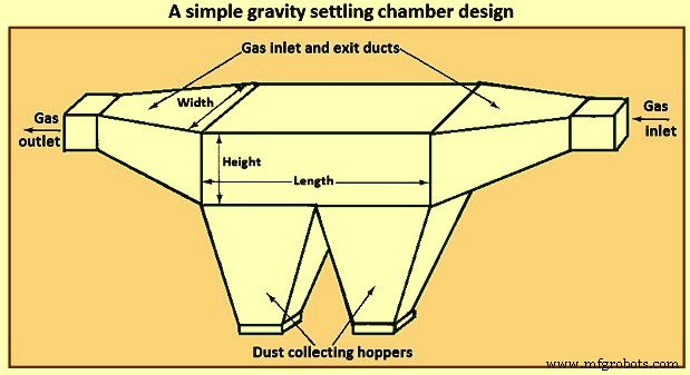
Рис. 1. Простая конструкция камеры гравитационного осаждения
При анализе работы отстойника ключевой характеристикой является характер потока газа через устройство. В связи с этим можно выделить три основные идеализированные ситуации течения, а именно (i) ламинарный поток, (ii) поршневой поток (скорость, равномерная по всему поперечному сечению) без вертикального перемешивания частиц и (iii) поршневой поток с полным вертикальным перемешиванием частиц. частицы.
Ламинарное течение характеризуется профилем скорости параболического типа. Такое течение реализуется только при числах Рейнольдса меньших, чем при переходе к турбулентному течению. В ламинарном потоке время, необходимое для осаждения частицы на высоте «h» над полом камеры, равно «h/V», где V — скорость осаждения частицы. Вертикальное перемешивание частиц отсутствует при ламинарном течении. Эффектом броуновского движения обычно пренебрегают по сравнению с устойчивым нисходящим движением из-за оседания.
В отстойнике с ламинарным потоком профиль скорости газа является параболическим, и когда частица оседает ниже центральной линии тока, она сталкивается с жидкостью, движущейся медленнее, и, таким образом, время ее пребывания в камере увеличивается по сравнению с тем, что было на более высокой линии тока. С другой стороны, частицы, изначально находящиеся над центральной линией тока, сталкиваются с более быстрыми линиями тока по мере своего падения, пока не пересекают центральную линию тока.
Вторая категория потока – поршневой поток без вертикального перемешивания частиц. Этот тип потока в некотором смысле является приближением к ламинарному потоку в том смысле, что вертикальное перемешивание частиц по-прежнему игнорируется, но предполагается плоский профиль скорости, и все частицы оседают со своими скоростями осаждения. Второй тип потока представляет собой поршневой поток без вертикального перемешивания частиц. В этой ситуации предполагается, что частицы равномерно распределяются по входу в камеру. Собирается ли частица, определяется исключительно высотой «h» на ее входе над собирающей поверхностью. Критическая высота «h*» может быть определена таким образом, что все частицы, входящие с «h», меньшим или равным «h*», собираются, а те, для которых «h» больше, чем «h*», ускользают от сбора.
Третья категория, поршневой поток с тщательным вертикальным перемешиванием, представляет собой турбулентный поток. В отстойнике с турбулентным потоком предполагается, что скорость газа одинакова по всей камере из-за турбулентного перемешивания. Кроме того, турбулентное перемешивание в сердцевине камеры подавляет тенденцию частиц к оседанию и поддерживает однородную концентрацию частиц по вертикали по всей камере. Можно предположить, что удаление путем осаждения происходит в тонком слое на дне камеры.
Течение в прямоугольном канале можно считать турбулентным, если число Рейнольдса больше 4000. В отстойнике с ламинарным потоком частицы оседают на любой высоте над полом камеры, при этом ключом к анализу является расчет общего времени пребывания частиц при их падении поперек линий тока. Механизм сбора в отстойнике с турбулентным потоком, хотя в конечном счете и основан на осаждении частиц под действием силы тяжести, несколько отличается от такового в камере с ламинарным потоком. Разница обусловлена турбулентным течением в камере. В объемном потоке в камере турбулентное перемешивание происходит достаточно интенсивно, так что частицы захлестываются потоком и не оседают. Предполагается, что турбулентное перемешивание поддерживает постоянную концентрацию частиц по высоте камеры. Можно предположить, что очень близко к полу камеры существует тонкий слой, через который частицы оседают на небольшом расстоянии от пола. Таким образом, как только частица, энергично перемешанная в ядре потока, попадает в этот слой, она оседает на пол.
Циклонные сепараторы
Циклонные сепараторы представляют собой газоочистные устройства, использующие центробежную силу, создаваемую вращающимся газовым потоком, для отделения частиц от газа. Стандартный циклонный сепаратор с тангенциальным входом и вертикальным обратным потоком показан на рис. 2. Поток газа вынужден следовать изогнутой геометрии циклона, в то время как инерция частиц в потоке заставляет их двигаться к внешней стенке, где они сталкиваются и собрал. На частицу массы «m», движущуюся по окружности радиуса «r» с тангенциальной скоростью «vA», действует центробежная сила «m(vA)2/r». При типичном значении «vA» =10 м/с, «r» =0,5 м эта сила в 20,4 раза больше силы тяжести, действующей на ту же частицу. Таким образом, можно видеть, что для геометрии циклона может быть достигнуто существенное увеличение силы, действующей на частицу, по сравнению с силой только осаждения.
В циклоне частицы вращающегося газового потока постепенно приближаются к внешней стенке по мере прохождения через устройство. Как показано на рис. 2, газовый поток может совершить несколько полных оборотов при движении от одного конца устройства к другому. Для конструкции циклонного сепаратора заданный расход газа, внутренний и внешний радиусы, длина корпуса циклона должны обеспечивать достижение требуемой эффективности улавливания частиц заданного размера. Поскольку длина корпуса циклона связана через расход газа с количеством оборотов, совершаемых газовым потоком, конструкция часто состоит из расчета количества оборотов, необходимого для достижения заданной эффективности улавливания.
Существует множество конструкций циклонных сепараторов, отличающихся тем, как вращательное движение сообщается газовому потоку. Обычные циклоны могут быть трех категорий, а именно (i) циклоны с обратным потоком (с тангенциальным входом и осевым входом), (ii) прямоточные циклоны и (iii) крыльчатые коллекторы.
На рис. 2 показан обычный циклон с обратным потоком и тангенциальным входом. Грязный газ поступает в верхнюю часть циклона и получает вращательное движение благодаря тангенциальному входу. Частицы прижимаются к стене под действием центробежной силы, а затем падают на стену под действием силы тяжести. В нижней части циклона газовый поток меняет направление, образуя внутреннее ядро, которое выходит в верхней части циклона. В циклоне с осевым входом и обратным потоком входящий газ вводится вниз по оси циклона, при этом центробежное движение передается постоянными лопастями вверху.
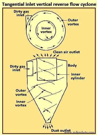
Рис. 2. Циклон с тангенциальным входом и вертикальным обратным потоком
В прямоточных циклонах внутренний вихрь воздуха выходит снизу (а не в обратном направлении), при этом начальное центробежное движение сообщается лопатками вверху. Этот тип часто используется в качестве предварительной очистки для удаления крупных частиц. Основными преимуществами этого циклона являются низкий перепад давления и высокий объемный расход.
В коллектор крыльчатки газы поступают нормально к многолопастной крыльчатке и выметаются крыльчаткой по ее окружности, а частицы выбрасываются в кольцевую щель по периферии циклона. Основным преимуществом этого циклона является его компактность. Основным недостатком циклона является склонность к засорению из-за твердых отложений в циклоне.
Циклоны могут быть изготовлены из любого материала, металла или керамики. Они способны выдерживать высокие температуры, абразивные частицы или коррозионную атмосферу. Необходимо, чтобы внутренняя поверхность была гладкой, чтобы собранные частицы могли легко скользить по стенке в бункер. В циклоне нет движущихся частей, поэтому его работа обычно проста и относительно не требует обслуживания. Низкие капитальные затраты и отсутствие обслуживания делают их идеальными для использования в качестве предварительных очистителей для более эффективных устройств конечного контроля, таких как электрофильтры. Хотя циклоны традиционно рассматривались как улавливатели с относительно низкой эффективностью, некоторые доступные в настоящее время циклоны могут достигать эффективности, превышающей 98% для частиц размером более 5 микрометров. Обычно эффективность циклонов достигает 90 % для частиц размером от 15 до 20 микрометров.
На рис. 3 показано вхождение частицы по касательной в горизонтальную плоскость вращающегося газового потока при r3. Из-за центробежной силы «m(vA)2/r» частица движется наружу поперек линий тока. Его вектор скорости имеет тангенциальную составляющую (vA) и радиальную составляющую (Vr). Существует также осевая составляющая (vZ).
Так называемый циклонный сепаратор с ламинарным потоком не имеет ламинарного потока в смысле отстойной камеры с ламинарным потоком, а представляет собой поток без трения, в котором линии тока повторяют контуры циклона, как показано на рис. 3.
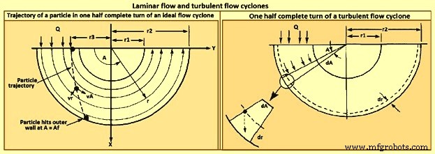
Рис. 3. Циклоны с ламинарным и турбулентным потоком
Модель турбулентного циклона-сепаратора представлена на рис. 3. Из-за турбулентного перемешивания концентрация частиц считается равномерной по всему циклону, и, как и в случае турбулентного отстойника, удаление происходит поперек тонкого слоя при внешняя стена.
Эффективность улавливания циклона увеличивается с увеличением (i) размера частиц, (ii) плотности частиц, (iii) скорости газа на входе, (iv) длины корпуса циклона, (v) количества оборотов газа и (vi) гладкости стенки циклона. С другой стороны, эффективность циклона снижается с увеличением (i) диаметра циклона, (ii) диаметра газоотводящего канала и (iii) площади входа газа. Для любого конкретного циклона, соотношение размеров которого фиксировано, эффективность улавливания увеличивается по мере уменьшения диаметра циклона. Конструкция циклонного сепаратора представляет собой компромисс между эффективностью сбора, перепадом давления и размером. Higher efficiencies need higher pressure drops (i.e., inlet gas velocities) and larger sizes (i.e. body length). The dimensions required to specify a tangential-entry, reverse-flow cyclone are shown in Fig 4.
Besides collection efficiency the other major consideration in cyclone specification is pressure drop. While higher efficiencies are achieved by forcing the gas through the cyclone at higher velocities, to do so results in an increased pressure drop. Since increased pressure drop needs increased energy input into the gas, there is ultimately an economic trade-off between collection efficiency and operating cost. Cyclone pressure drops normally range from 250 Pa to 4,000 Pa.
Electrostatic precipitator
ESP is one of the most widely used particulate control device. It has wide size ranges. The ESP chamber consists of two electrodes, the discharge and the collecting electrodes. Between the electrodes, the gas contains free electrons, ions, and charged particles. The species contributing to the space charge density are ions, electrons, and charged particles. The gas molecules capture all the free electrons so that only the ions and charged particles contribute space charge density. Actually, ionic current flows in the direction of the electric field consisting of ions charged with the same polarity as the charging electrode and moving to the collecting electrode. The ions migrate to the collecting electrode with a velocity large enough to be unaffected by the turbulent flow in the chamber.
The basic principle of operation of the ESP is that the particles are charged, and then an electric field is imposed on the region through which the particle-laden gas is flowing, exerting an attractive force on the particles and causing them to migrate to the oppositely charged electrode at right angles to the direction of gas flow. ESP differs from mechanical methods of particle separation in that the external force is applied directly to the individual particles rather than indirectly through forces applied to the entire gas stream (e.g. in a cyclone separator). Particles collect on the electrode. If the particles collected are liquid, then the liquid flows down the electrode by gravity and it is removed at the bottom of the device. If the particles are solid, the collected layer on the electrode is removed periodically by rapping the electrode.
Particle charging is achieved by generating ions by means of a corona established surrounding a highly charged electrode like a wire. The electric field is applied between that electrode and the collecting electrode. If the same pair of electrodes serves for particle charging and collecting, the device is called a single-stage ESP (Fig 4). A wire serving as the discharge electrode is suspended down the axis of a tube and held in place by a weight attached at the bottom. The sides of the cylinder form the collecting electrode. The collected particles which form a layer on the collecting electrode are removed to the dust hopper by rapping the collecting electrode. In a two-stage ESP, separate electrode pairs perform the charging and collecting functions.
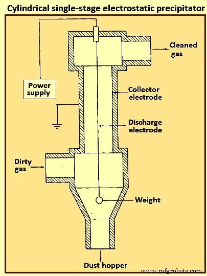
Fig 4 Cylindrical single-stage electrostatic precipitator
Most industrially generated particles are charged during their formation by such means as flame ionization and friction, but normally only to a low or moderate degree. These natural charges are far too low for electrostatic precipitation. The high-voltage DC (direct current) corona is the most effective means for particle charging and is universally used for electrostatic precipitation. The corona is formed between an active high voltage electrode such as a fine wire and a passive ground electrode such as a plate or pipe. The corona surrounding the discharge electrode can lead to the formation of either positive or negative ions which migrate to the collecting electrode. The ions, in migrating from the discharging to the collecting electrode, collide with the particulate matter and charge the particles.
Since the gas molecule ions are many orders of magnitude smaller than even the smallest particles and because of their great number, virtually all particles that flow through the device become charged. The charged particles are then transported to the collecting electrode, to which they are held by the electrostatic attraction. The particles build a thickening layer on the collecting electrode. The charge slowly bleeds from the particles to the electrode. As the layer grows, the charges on the most recently collected particles are to be conducted through the layer of previously collected particles. The resistance of the dust layer is called the dust resistivity.
As the particle layer grows in thickness, the particles closest to the plates lose most of their charge to the electrode. As a result, the electrical attraction between the electrode and these particles is weakened. However, the newly arrived particles on the outside layer have a full charge. Because of the insulating layer of particles, these new particles do not lose their charge immediately and thus serve to hold the entire layer against the electrode. Finally, the layer is removed by rapping, so that the layer breaks up and falls into a collecting hopper. ESPs are normally employed for gas cleaning when the volumetric throughput of gas is high.
The mechanism for particle charging in a ESP is the generation of a supply of ions which attach themselves to the particles. The corona is the mechanism for forming ions. The corona can be either positive or negative. A gas normally has a few free electrons and an equal number of positive ions, a situation which is exploited in generating a corona. When a gas is placed between two electrodes, small amount of current results as the free electrons migrate to the positive electrode and the positive ions migrate to the negative electrode.
In the positive corona discharge electrode, the wire in the cylindrical ESP (Fig 4) is at a positive potential. The few free electrons normally present in the gas migrate toward the wire. As the electrons approach the wire, the electrons’ energy is increased because of an increase in the attractive force. These free electrons collide with gas molecules, the collision leading in some cases to the ejection of an electron from the molecule, producing two free electrons and a positive ion. The two free electrons continue toward the positive electrode, gaining energy, until they collide with two more gas molecules, producing four free electrons and two positive ions. This process is referred to as an electron avalanche.
The positive ions formed migrate to the negative electrode. It is these positive ions which migrate across the entire device to the negative electrode that collide with and attach to the particles in the gas. The region immediately surrounding the wire in which the electron avalanche is established is the corona. Thus, with a positive corona the particles become positively charged. The term ‘corona’ arises from the fact that the electron avalanche is frequently accompanied by the production of light. In the negative corona the discharge electrode is maintained at a negative potential.
The electron avalanche begins at the outer surface of the wire and proceeds radially outward. Close to the wire the electrons are sufficiently energetic to form positive ions upon collision with gas molecules, thus initiating the electron avalanche. The positive ions formed migrate the short distance to the wire. As the electrons migrate outward into a region of lower electric field strength, they are slowed down by collisions with gas molecules. These electrons eventually have lower energy than those which are accelerated toward the positive electrode in the positive corona. These relatively low energy electrons, rather than ejecting an electron from the gas molecule upon collision, are absorbed by the gas molecules to produce negative ions. The formation of negative ions, which begins to occur at the outer edge of the corona, essentially absorbs all the free electrons produced in the electron avalanche at the wire surface. These negative ions then migrate to the positive electrode, in the course of which attaching to gas molecules and forming negative ions.
For a negative corona to be effective, it is necessary that the gas molecules can absorb free electrons to form negative ions. Sulphur dioxide is one of the best electron absorbing gases of those present in flue gases. Oxygen, CO2, and H2O are also effective electron absorbers. The negative corona is normally more stable than the positive corona, so it is preferred in most industrial applications. A by-product of the negative corona is the production of ozone (O3). The positive corona does not need an electron-absorbing gas.
As the ESP is operated, a layer of the collected material builds up on the collecting electrode. Particle deposits on the precipitator collection surface are to possess at least a small degree of electrical conductivity in order to conduct the ion currents from the corona to ground. The minimum conductivity required is around 10 to the power -10 per ohm-centimeter (resistivity of 10 to the power 10 ohm-centimeter). This conductivity is small compared to that of ordinary metals but is much greater than that of good insulators such as silica and most plastics. The resistivity of a material is determined by establishing a current flow through a slab of known thickness of the material.
As long as the resistivity of the collected dust layer is less than about 10 to the power 10 ohm-centimeter, the layer surrender its charge to the electrode. At the room temperature, a typical dust has a resistivity of around 10 to the power 8 ohm-centimeter. This is because of a layer of water on the surface of the particles. As the temperature is increased beyond 100 deg C, the water is evaporated and the resistivity increases to a value characteristic of the collected solids. When the resistivity of the layer exceeds around 10 to the power 10 ohm-centimeter, the potential across the layer increases so that the voltage which can be maintained across the ESP decreases and the collection efficiency decreases. The electrical resistivity of collected particulate matter depends on its chemical composition, the constituents of the gas, and the temperature.
Particle charging in ESP occurs in the gas space between the electrodes where the gas ions generated by the corona bombard and become attached to the particles. The gas ions can reach concentrations as high as 10 to the power 15 ions per cubic meter. The level of charge attained by a particle depends on the gas ion concentration, the electric field strength, the conductive properties of the particle, and the particle size. A 1 micrometer particle typically acquires the order of 300 electron charges, whereas a 10 micrometer particle can attain 30,000 electron charges. Predicting the level of charge acquired by a particle is necessary in order to predict the particle’s migration velocity, on the basis of which the collection efficiency can be calculated for a given set of operating conditions.
There are actually two mechanisms by which particles become charged in an ESP. In the first mechanism particle charging occurs when ions which are migrating toward the collecting electrode encounter particles to which they become attached. In migrating between the electrodes the ions follow the electric flux lines, which are curves everywhere tangent to the electric field vector. When the particle first enters the device and is uncharged, the electric flux lines deflect toward the particle, resulting in the capture of even a larger number of ions than are captured if the ions have followed their normal path between the electrodes. As the particle becomes charged, ions begin to be repelled by the particle, reducing the rate of charging. Eventually, the particle acquires a saturation charge and charging ceases. This mechanism is called ion bombardment or field charging.
The second mode of particle charging is diffusion charging, in which the particle acquires a charge by virtue of the random thermal motion of ions and their collision with and adherence to the particles. Diffusion charging occurs as the ions in their random thermal motion collide with a particle and surrender their charge to it. In that sense the mechanism of diffusion charging is identical to that of the diffusion of uncharged vapour molecules to the surface of a particle. However, because both the particle and the ions are charged, the random thermal motion of the ions in the vicinity of a particle is influenced by an electrostatic force. This force gives rise to a tendency of the ions to migrate away from the particle as the particle charge increases. The overall flux of ions to a particle hence is both the random diffusive motion and the electrical migration.
The theories of both field and diffusion charging, in their full generality, are quite complex and have received a great deal of attention. Strictly speaking, field and diffusion charging occur simultaneously once a particle enters an ESP, and hence to predict the overall charge acquired by a particle, one is to consider the two mechanisms together. However, since the diffusion charging is predominant for particles smaller than around 1 micrometer in diameter and field charging is predominant for particles larger than around 1 micrometer, the two mechanisms frequently are treated in ESP design as if they occur independently. In doing so, one estimates the total charge on a particle as the sum of the charges resulting from each of the two separate mechanisms.
Filtration of particles from gas streams
A major class of particulate air pollution control devices relies on the filtration of particles from gas streams. A variety of filter media is employed, including fibrous beds, packed beds, and fabrics. Fibrous beds used to collect airborne particles are typically quite sparsely packed, usually only around 10 % of the bed volume being fibers. Packed bed filters consist of solid packing normally in a tube and tend to have higher packing densities than do fibrous filters. Both fibrous and packed beds are widely used in the ventilation systems. Fabric filters are frequently used to remove solid particles from industrial gases, whereby the dusty gas flows through fabric bags and the particles accumulate on the cloth.
The physical mechanisms by which the filtration is accomplished vary depending on the mode of filtration. Conventional sparsely packed fibrous beds can be viewed as assemblages of cylinders. In such a filter, the characteristic spacing between fibers is much larger than the size of the particles being collected. Thus the mechanism of collection is not simply sieving, in which the particles are trapped in the void spaces between fibers. Rather, the removal of particles occurs by the transport of particles from the gas to the surface of a single collecting element. Because the filtration mechanisms in a fibrous bed can be analyzed in terms of a single collector, it is possible to describe them in considerable theoretical detail.
Packed-bed filters are sometimes viewed as assemblages of interacting, but essentially separate, spherical collectors, although the close proximity of individual packing elements casts doubt as to the validity of this approach. Because of the relatively closer packing in packed-bed filters, and the resulting difficulty of describing the particle collection process in clean theoretical terms, predicting collection in such systems is more empirically based than for fibrous filters. Fabric filter efficiencies must be predicted strictly empirically since the accumulated particle layer actually does the collecting.
A fibrous filter bed is viewed as a loosely packed assemblage of single cylinders. Even though the fibers are oriented in all directions in the bed, from a theoretical point of view the bed is treated as if every fiber is normal to the gas flow through the bed. The solid fraction of the filter is normally of the order of only 10 %. In addition, each fiber acts more or less independently as a collector. Thus, to compute the particle removal by a filter bed, one basically needs to determine the number of fibers per unit volume of the bed and then multiply that quantity by the efficiency of a single fiber.
The basis of predicting the collection efficiency of a filter bed is the collection efficiency of a single filter element in the bed. The filter element is taken as an isolated cylinder normal to the gas flow. Three distinct mechanisms as given below can be identified whereby particles in the gas reach the surface of the cylinder.
As per the first mechanism, the particles in a gas undergo Brownian diffusion which brings some particles in contact with the cylinder due to their random motion as they are carried past the cylinder by the flow. A concentration gradient is established after the collection of a few particles and acts as a driving force to increase the rate of deposition over that which occurs in the absence of Brownian motion. Because the Brownian diffusivity of particles increases as particle size decreases, it is normally expected that this removal mechanism is the most important for very small particles. When analyzing collection by Brownian diffusion, the particles are treated as diffusing mass-less points.
As per the second mechanism, interception takes place when a particle, following the streamlines of flow around a cylinder, is of a size sufficiently large that its surface and that of the cylinder come into contact. Thus, if the streamline on which the particle centre lies is within a distance Dp /2 of the cylinder, interception occurs. Here Dp is the particle diameter.
As per the third mechanism, inertial impaction occurs when a particle is unable to follow the rapidly curving streamlines around an obstacle and, because of its inertia, continues to move toward the obstacle along a path of less curvature than the flow streamlines. Thus, collision occurs because of the particle’s momentum. It is to be noted that the mechanism of inertial impaction is based on the premise that the particle has mass but no size, whereas interception is based on the premise that the particle has size but no mass.
Collection can also result from electrostatic attraction when either particles or fiber or both possess a static charge. These electrostatic forces can be either direct, when both particle and fiber are charged, or induced, when only one of them is charged. Such charges are normally not present unless deliberately introduced during the production of the fiber.
The size ranges in which the various mechanisms of collection are important are (i) Inertial impaction – greater than 1 micrometer, (ii) Interception – greater than 1 micrometer, (iii) diffusion – less than 0.5 micrometer, and (iv) electrostatic attraction – 0.01 micrometer to 5 micrometer. It is normal to analyze the mechanisms of collection separately and then combine the individual efficiencies to give the overall collection efficiency for the cylinder or other obstacle.
Most developments of particle collection assume, for lack of better information, that particles transported to the surface of a fiber are retained by the fiber. Experiments have shown, however, that for a variety of substances and filter media, the fraction of particles striking the collector surface which adhere is generally less than unity and can in some cases be as low as 0.5.
Industrial fabric filtration is normally accomplished in a so-called bag- house, in which the particle-laden gases are forced through filter bags. Particles are normally removed from the bags by gravity. Fig 5 shows three bag-house designs, in which cleaning is accomplished by vibration (Fig 5a), air jet [Fig 5b), or traveling ring [Fig 5c).
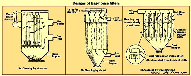
Fig 5 Designs of bag house filters
The fabric filtration process consists of three phases. First, particles collect on individual fibers by the above described mechanisms. Then an intermediate stage exists during which particles accumulate on previously collected particles, bridging the fibers. Finally, the collected particles form a cake in the form of a dust layer which acts as a packed bed filter for the incoming particles. As the dust layer accumulates, the pressure drop across the filter increases, and periodically the dust layer is to be dislodged into the hopper at the bottom to ‘regenerate’ the fabric bag. High efficiencies are attainable with fabric filters, particularly in treating combustion gases from the technological processes. To the extent that effective operation of an ESP depends on the presence of SO2 in the gas as an ionizable species, fabric filters can operate with no loss of efficiency with low-sulphur level.
Fabric filters consist of semi-permeable woven or felted materials which constitute a support for the particles to be removed. A brand-new woven filter cloth has fibers roughly 100 micrometers to 150 micrometers in diameter with open spaces between the fibers of 50 micrometers to 75 micrometers. Initially, the collection efficiency of such a cloth is low because most of the particles pass directly through the fabric. However, deposited particles quickly accumulate, and it is the deposited particle layer that enables the high-efficiency removal once a uniform surface layer has been established.
Although fiber mat filters are similar in some respects to fabric filters, they do not depend on the layer of accumulated particles for high efficiency. Fiber mat filters generally are not cleaned but are discarded. They are ordinarily used when particle concentrations are low, so that reasonable service life can be achieved before discarding.
In a fabric filter the particle layer performs the removal task. As the layer of collected particles grows in thickness, there is an increase in the pressure drop across the particle layer and the underlying fabric. The two major considerations in the design of a fabric filter assembly are the collection efficiency and the pressure drop as a function of time of operation (since the last cleaning). The collection efficiency depends on the local gas velocity and the particle loading on the fabric.
Fabric filters offer the several advantages such as (i) they can achieve very high collection efficiencies even for very small particles, (ii) they can be used for a wide variety of particles, (iii) they can operate over a wide range of volumetric flow rates, and (iv) they need only moderate pressure drops. The limitations of fabric filters are namely (i) operation is to be carried out at temperatures lower than that at which the fabric is destroyed, or its life is shortened to an uneconomical degree, (ii) gas or particle constituents which attack the fabric or prevent proper cleaning, such as sticky particles difficult to dislodge, are to be avoided, and (iii) bag houses need large floor areas. The advantages of fabric filter bag houses clearly outweigh their limitations.
Wet collectors
Wet collectors, or scrubbers, employ water washing to remove particles directly from a gas stream. Scrubbers can be grouped broadly into two main classes namely (i) those in which an array of liquid drops (sprays) form the collecting medium, and (ii) those in which wetted surfaces of various types constitute the collecting medium. The first class includes spray towers and venturi scrubbers, while the second includes plate and packed towers.
Scrubbing is a very effective means of removing small particles from a gas. Removal of particles results from collisions between particles and water drops. In the humid environment of a scrubber, small, dry particles also grow in size by condensation of water and thereby become easier to remove. Re-entrainment of particles is avoided since the particles become trapped in droplets or in a liquid layer. A scrubber also provides the possibility of simultaneously removing soluble gaseous pollutants. The particle-laden scrubbing liquid is to be disposed of, a problem not encountered in dry methods of gas cleaning.
A spray scrubber is a device in which a liquid stream is broken into drops, approximately in the range 0.1 mm to 1 mm in diameter, and introduced into the particle laden gas stream. The array of moving drops becomes a set of targets for collection of the particles in the gas stream. Collection efficiency is computed by considering the efficiency of a single spherical collector and then summing over the number of drops per unit volume of gas flow. The relative motion between the drops and particles is an important factor in the collection efficiency since capture occurs by impaction and direct interception. Diffusion is also important for smaller particles.
There are two general types of spray scrubbers. The first class comprises those having a preformed spray where drops are formed by atomizer nozzles and sprayed into the gas stream. These include (i) counter-current gravity tower, where drops settle vertically against the rising gas stream, (ii) cross-current tower, where drops settle through a horizontal gas stream, and (iii) co-current tower, where spray is horizontal into a horizontal gas stream.
The second class comprises those in which the liquid is atomized by the gas stream itself. Liquid is introduced more or less in bulk into a high-velocity gas flow which shatters the liquid into drops. Devices in this class are called venturi scrubbers since the high velocity gas flow is achieved in a venturi (a contraction). Fig 6 shows four types of wet collection equipment.
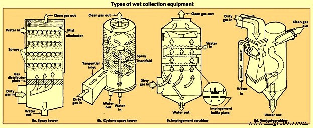
Fig 6 Types of wet collection equipment
The simplest type of wet collector is a spray tower into which water is introduced by means of spray nozzles (Fig 6a). Gas flow in a spray chamber is counter-current to the liquid, the configuration leading to maximum efficiency. Collection efficiency can be improved over the simple spray chamber with the use of a cyclonic spray tower, as shown in Fig 6b. The liquid spray is directed outward from nozzles in a central pipe. An unsprayed section above the nozzles is provided so that the liquid drops with the collected particles have time to reach the walls of the chamber before exit of the gas. An impingement plate scrubber, as shown in Fig 6c, consists of a tower containing layers of baffled plates with holes (5,000 to 50,000 per square meter) through which the gas must rise and over which the water must fall. Highest collection efficiencies of wet collectors are obtained in a venturi scrubber, shown in Fig 6d, in which water is introduced at right angles to a high-velocity gas flow in a venturi tube, resulting in the formation of very small water droplets by the flow and high relative velocities of water and particles. The high gas velocity is responsible for the breakup of the liquid. Aside from the small droplet size and high impingement velocities, collection is enhanced through particle growth by condensation. Different types of particle scrubbing devices are described below.
Plate scrubber – It is a vertical tower containing one or more horizontal plates (trays). Gas enters the bottom of the tower and must pass through perforations in each plate as the gas flows counter-current to the descending water stream. Plate scrubbers are normally named for the type of plates they contain (e.g. sieve plate tower). Collection efficiency increases as the diameter of the perforations decreases. A cut diameter, that collects with 50 % efficiency, of around 1 micrometer aerodynamic diameter can be achieved with 3.2 mm diameter holes in a sieve plate.
Packed-bed scrubber – It operates similarly to packed-bed gas absorber. Collection efficiency increases as packing size decreases. A cut diameter of 1.5 micrometers aerodynamic diameter can be attained in columns packed with 2.5 cm elements.
Spray scrubber – In this scrubber, particles are collected by liquid drops which have been atomized by spray nozzles. Horizontal and vertical gas flows are used, as well as spray introduced co-current, counter-current, or cross-flow to the gas. Collection efficiency depends on droplet size, gas velocity, liquid / gas ratio, and droplet trajectories. For droplets falling at their terminal velocity, the optimum droplet diameter for fine-particle collection lays in the range 100 micrometers to 500 micrometers. Gravitational settling scrubbers can achieve cut diameters of around 2 micrometers. The liquid / gas ratio is in the range 0.001 cum to 0.01 cum per cum of gas treated.
Venturi scrubber – A moving gas stream is used to atomize liquids into droplets. High gas velocities (60 m/sec to 120 m/s) lead to high relative velocities between gas and particles and promote collection.
Cyclone scrubber – Drops can be introduced into the gas stream of a cyclone to collect particles. The spray can be directed outward from a central manifold or inward from the collector wall.
Baffle scrubber – In this scrubber, there are changes in gas flow velocity and direction induced by solid surfaces.
Impingement-entrainment scrubber – The gas is forced to impinge on a liquid surface to reach a gas exit. Some of the liquid atomizes into drops which are entrained by the gas. The gas exit is designed so as to minimize the loss of entrained droplets.
Fluidized-bed scrubber – A zone of fluidized packing is provided where gas and liquid can mix intimately. Gas passes upward through the packing, while liquid is sprayed up from the bottom and / or flows down over the top of the fluidized layer of packing.
The collection efficiency of wet collectors can be related to the total energy loss in the equipment. The higher is the scrubber power per unit volume of gas treated, the better is the collection efficiency. Almost all the energy is introduced in the gas, and thus the energy loss can be measured by the pressure drop of gas through the unit. The major advantage of wet collectors is the wide variety of types, allowing the selection of a unit suitable to the particular removal problem. As regards disadvantages, high pressure drops (and hence energy requirements) are to be maintained, and the handling and disposal of large volumes of scrubbing liquid are to be undertaken.
In case of spray scrubbing, the conceptually simplest of the devices is a gravity spray chamber. Water droplets are introduced at the top of an empty chamber through atomizing nozzles and fall freely at their terminal settling velocities counter-currently through the rising gas stream. The particle-containing liquid collects in a pool at the bottom and is to be pumped out for treatment to remove the solids, and the cleaned liquid is normally recycled to the tower. The overall efficiency of a spray tower increases as the collection efficiency of a single drop increases, as the length of the chamber increases, and as the ratio of the volumetric flow rate of water to that of gas increases. It increases as the diameter of the drops decreases.
Venturi scrubbers are used when high collection efficiencies are needed and when most of the particles are smaller than 2 micrometers in diameter. There are a number of examples, in fact, where a venturi scrubber is the only practical device for a gas-cleaning application. If the particles to be removed are sticky, flammable, or highly corrosive, for example, ESPs and fabric filters cannot be used. Venturi scrubbers are also the only high-efficiency particulate collectors which can simultaneously remove gaseous species from the effluent stream.
The distinguishing feature of a venturi scrubber is a constricted cross section or throat through which the gas is forced to flow at high velocity. A typical venturi scrubber configuration is shown in Fig 7. The configuration includes a converging conical section where the gas is accelerated to throat velocity, a cylindrical throat, and a conical expander where the gas is slowed down. Liquid can be introduced either through tangential holes in the inlet cone or in the throat itself. In the former case, the liquid enters the venturi as a film on the wall and flows down the wall to the throat, where it is atomized by the high-velocity gas stream. In the latter, the liquid is injected perpendicular to the gas flow in the throat, atomized, and then accelerated. Gas velocities in the range 60 m/sec to 120 m/sec are achieved, and the high relative velocity between the particle laden gas flow and the droplets promotes collection. The collection process is essentially complete by the end of the throat. Because they operate at much higher velocities than ESPs precipitators or bag houses, venturi scrubbers are physically smaller and can be economically made of corrosion-resistant materials. Venturis have the simplest configuration of the scrubbers and are the smallest in size. Fig 7 shows the comparison of the efficiency of venturi scrubber with the efficiencies of other gas cleaning devices.
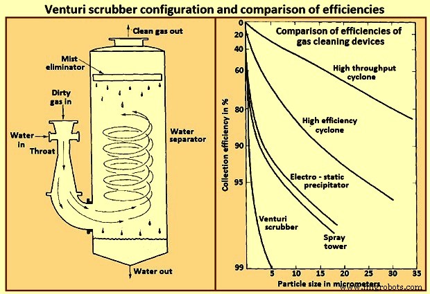
Fig 7 Venturi scrubber configuration and comparison of efficiencies
A typical range of liquid to gas flow rate ratios for a venturi scrubber is 0.001 cum to 0.003 cum of liquid per cum of gas. At the higher liquid / gas ratios, the gas velocity at a given pressure drop is reduced, and at lower ratios, the velocity is increased. For gas flow rates exceeding about 1,000 cum / minute venturi scrubbers are normally constructed in a rectangular configuration in order to maintain an equal distribution of liquid over the throat area.
Производственный процесс
- Обзор поставщиков медицинских услуг RTLS (и предлагаемые ими технологии)
- Контроль доступа с помощью QR, RFID и проверки температуры
- Управление датчиком и исполнительным механизмом Raspberry Pi
- Возможности и преимущества технологий и систем роботизированного контроля
- Чистота IS iFP Системы очистки и промывки деталей
- Сварочные газы:101 почему мы их используем и их типы
- Области применения и преимущества использования решения для мониторинга газа
- 5 отраслей, где системы обнаружения газа очень важны
- SCADA-системы и индустрия 4.0
- Детали и элементы систем станков с ЧПУ