



Siemens Sinumerik 840D: справочник аварий для экспертной диагностики
Список аварий Siemens Sinumerik 840D (840D/840Di/810D и похожие) для наладчиков и персонала ТО, работающих на станках с ЧПУ Sinumerik.
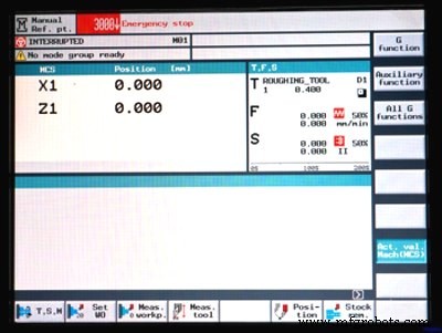
Список аварий Sinumerik 840D
Ниже приведен фрагмент списка (полный список очень объемен):
- 1000 — System error %1
- 1001 — System error %1
- 1002 — System error %1
- 1003 — Alarm pointer for this self-clearing alarm %1 is zero
- 1004 — Alarm reaction to NCK alarm incorrectly configured
- 1005 — Operating system error %1 parameter %2 %3 %4
- 1010 — Channel %1 system error %2 action %3
- 1011 — Channel %1 %3 %4 system error %2
- 1012 — Channel %1 system error %2 %3 %4
- 1013 — Channel %1 system error %2
- 1014 — Channel %1 system error %2
- 1015 — Channel %1 axis %2 system error %3
- 1016 — Channel %1 axis %2 system error %3
- 1017 — Channel %1 axis %2 system error %3
- 1018 — Floating point arithmetic error in channel %1 task %2 station %3 FPU state %4
- 1019 — Floating point arithmetic error at address %3 in channel %1 task %2 FPU state %4
- 1030 — System error in link module error code %1 error type %2
- 1031 — Link module generated an unspecified error %1 NCU %2 %3 %4
- 1100 — No valid firmware
- 1160 — Assertion failed in %1: %2
- 2000 — PLC sign-of-life monitoring
- 2001 — PLC has not started up
- 2100 — NCK battery warning threshold reached
- 2101 — NCK battery alarm
- 2102 — NCK battery alarm
- 2110 — NCK temperature alarm
- 2120 — NCK fan alarm
- 2130 — 5V/24V encoder or 15V D/A converter under voltage
- 2140 — The actual service switch position forces a SRAM to be cleared at the next Power On
- 2190 — Hardware plug-in module for communication with the digitizer missing
- 2192 — No NCU link module exists, MD %1 reset
- 2193 — "Safety Integrated" is not available for link axis %1
- 2195 — Channel %1 axis %2 high-speed punching/nibbling not possible via link
- 2196 — Link axis active and $MN_MM_SERVO_FIFO_SIZE != %1
- 2900 — Reboot is delayed
- 3000 — Emergency stop
- 3001 — Internal emergency stop
- 4000 — Channel %1 machine data %2[%3] has gap in axis assignment
- 4001 — Channel %1 axis %2 defined for more than one channel via machine data %3
- 4002 — Channel %1 machine data %2[%3] assigns an axis not defined in channel
- 4003 — Axis %1 incorrect assignment of master channel in machine data %2
- 4004 — Channel %1 machine data %2 axis %3 defined repeatedly as geometry axis
- 4005 — Maximum number of axes in channel %1 exceeded. Limit %2
- 4007 — Axis %1 incorrect assignment of master NCU in machine data %2
- 4010 — Invalid identifier used in machine data %1[%2]
- 4011 — Channel %1 invalid identifier used in machine data %2[%3]
- 4012 — Invalid identifier used in machine data %1[%2]
- 4013 — Invalid NCU link configuration by machine data %1 = %2 , on NCU_1 = %3
- 4014 — Axis %1 defined several times in %2
- 4016 — Axis %1 already used by NCU %2
- 4017 — Axis container %1, location %2 already used by NCU %3
- 4018 — Axis container %1, location %2 not used by any channel
- 4019 — Axis container %1 advance not allowed with current status of NCU %2
- 4020 — Identifier %1 used several times in machine data %2
- 4021 — Channel %1 identifier %2 used several times in machine data %3
- 4022 — Axis container %3 switch not allowed: ext. zero offset active channel %1 axis %2
- 4023 — Axis container %1 switch not allowed, axis container %2 switch active
- 4024 — Invalid axis configuration due to missing axis container machine data
- 4025 — Axis container %3 switch not allowed: master/slave active channel %1 axis %2
- 4026 — Machine data %1[%2], link axis NC%3_AX%4 not used by any channel
- 4027 — Notice: MD %1 was also changed for the other axes of axis container %2
- 4028 — Notice! The axial MDs of the axes of the axis containers were matched.
- 4029 — Notice: the axial MDs in axis container %1 will be matched on the next power-up
- 4030 — Channel %1 axis identifier missing in machine data %2[%3]
- 4031 — Channel %1 link axis %2 defined for more than one channel in machine data %3
- 4032 — Channel %1 wrong identifier for facing axis in %2
- 4033 — Notice: NCU link communication still not connected
- 4034 — Local link axis %1 is not allowed for different interpolation cycle time = %2/%3
- 4035 — Interpolation cycle from NCU%1 = %2 does not match NCU%3 = %4
- 4036 — Wrong NCU link configuration by MD %1
- 4040 — Channel %1 axis identifier %2 not consistent with machine data %3
- 4045 — Channel %1 conflict between machine data %2 and machine data %3
- 4050 — NC code identifier %1 cannot be reconfigured to %2
- 4060 — Standard machine data loaded
- 4062 — Backup data loaded
- 4065 — Buffered memory was restored from backup medium (potential loss of data!)
- 4066 — Buffered memory of FFS restored from backup medium (potential loss of data!)
- 4070 — Normalizing machine data has been altered
- 4073 — Compile cycle functions define machine data number %1 several times
- 4075 — Machine data %1 (and maybe others) not altered due to missing permission level %2
- 4076 — %1 Machine data could not be altered with permission level %2
- 4077 — New value %1 of MD %2 not set. Requested %3 bytes too much %4 memory.
- 4080 — Incorrect configuration of indexing axis in MD %1
- 4090 — Too many errors during power-up
- 4100 — System cycle time/scan time divider corrected for digital drive
- 4102 — Default values for drive cycle times differ
- 4110 — IPO factor increased to %1
- 4111 — PLC cycle increased to %1 ms
- 4112 — Servo cycle changed to %1 ms
- 4113 — Sysclock cycle changed to %1 ms
- 4114 — Error in DP cycle of SDB1000
- 4115 — Time ratio communication to Ipo changed to %1
- 4150 — Channel %1 invalid M function sub program call configured
- 4152 — Illegal configuration of the "Block display with absolute values" function
- 4160 — Channel %1 invalid M function number configured for spindle switchover
- 4170 — Invalid M function number for channel synchronisation assigned
- 4180 — Invalid M function number assigned to enable ASUP
- 4181 — Channel %1 invalid assignment of an M auxiliary function number
- 4182 — Channel %1 invalid M auxiliary function number in %2%3, MD reset
- 4183 — Channel %1 M auxiliary function number %2 used several times (%3 and %4)
- 4184 — Channel %1 illegally predefined auxiliary function in %2%3, MD reset
- 4185 — Channel %1 illegal auxiliary function configured %2 %3 %4
- 4200 — Channel %1 geometry axis %2 must not be declared a rotary axis
- 4210 — Channel %1 spindle %2 declaration as rotary axis missing
- 4215 — Channel %1 spindle %2 declaration as modulo axis missing
- 4220 — Channel %1 spindle %2 declared repeatedly
- 4225 — Channel %1 axis %2 declaration as rotary axis missing
- 4230 — Channel %1 data alteration from external not possible in current channel state
- 4240 — Runtime overflow for IPO cycle or position controller cycle, IP %1
- 4250 — FastPlcCom functionality not available
- 4252 — PLCIO read error: %1
- 4254 — PLCIO write error: %1
- 4260 — Machine data %1 illegal
- 4270 — Machine data %1 assigns not activated NCK input/output byte %2
- 4275 — Machine data %1 and %2 both assign the same NCK output byte no. %3 several times
- 4280 — Assignment of NCK input/output byte via MD %1[%2] does not match hardware configuration
- 4282 — Hardware of external NCK outputs assigned repeatedly
- 4285 — Error on terminal block %1, error code %2
- 4290 — Local P-bus sign-of-life monitoring
- 4291 — Module in local P-bus slot %1 error codes %2 %3 %4
- 4300 — Declaration in MD %1 is not allowed for geometry axis/spindle %2.
- 4310 — Declaration in MD %1 index %2 is not allowed.
- 4320 — Axis %1 function %2 %3 and %4 not allowed
- 4334 — Channel %1 The amount of fine correction in parameter %2 of the orientable toolholder %3 is too large
- 4336 — Channel %1 orientable toolholder no. %2 for orientation transformation %3 does not exist
- 4338 — Channel %1 invalid transformation type '%2' in toolholder %3 for orientation transformer %4
- 4340 — Channel %1 block %2 invalid transformation type in transformation no. %3
- 4341 — Channel %1 block %2 no data set available for transformation no. %3
- 4342 — Channel %1 invalid machine data for general 5-axis transformation error no. %2
- 4343 — Channel %1 attempt made to change the machine data of an active transformation.
- 4345 — Channel %1 invalid configuration in chained transformation no.%2
- 4346 — Channel %1 invalid geoaxis assignment in machine data %2[%3]
- 4347 — Channel %1 invalid channel axis assignment in machine data %2[%3]
- 4350 — Channel %1 axis identifier %2 machine data %3 not consistent with machine data %4
- 4400 — MD alteration will cause reorganisation of buffered memory (loss of data!)
- 4502 — Channel %1 anachronism %2(%3) -> %4
- 5000 — Communication job not executable %1
- 6000 — Memory reorganized using standard machine data
- 6010 — Channel %1 data block %2 not or not completely created, error code %3
- 6020 — Machine data have been altered – now memory is reorganized
- 6030 — Limit of user memory has been adapted
- 6035 — Instead of %1 KB the system has only %2 KB of free user memory of type "%3"
- 6100 — Error while creating %1, error number %2 %3
- 6401 — Channel %1 tool change not possible: Empty location for tool %2 Duplo no. %3 on magazine %4 not available.
- 6402 — Channel %1 tool change not possible. Magazine no. %2 not available
- 6403 — Channel %1 tool change not possible. Magazine location number %2 on magazine %3 not available.
- 6404 — Channel %1 tool change not possible. Tool %2 not available or not usable
- 6405 — Channel %1 command %2 has invalid PLC acknowledge parameter %3 – identifier %4
- 6406 — Channel %1 PLC acknowledge for command %2 is missing
- 6407 — Channel %1 tool %2 cannot be placed in magazine %3 on location %4.Invalid definition of magazine!
- 6410 — TO unit %1 tool %2 / Duplo no. %3 has reached its pre warning limit with D = %4
- 6411 — Channel %1 tool %2 / Duplo no. %3 has reached its prewarning limit with D = %4
- 6412 — TO unit %1 tool %2 / Duplo no. %3 has reached its monitoring limit with D = %4
- 6413 — Channel %1 tool %2 / Duplo no. %3 has reached its monitoring limit with D = %4
- 6421 — Channel %1 tool move not possible. Empty location for tool %2 Duplo no. %3 on magazine %4 not available.
- 6422 — Channel %1 tool move not possible. Magazine no. %2 not available.
- 6423 — Channel %1 tool move not possible. Location %2 on magazine %3 not available.
- 6424 — Channel %1 tool move not possible. Tool %2 not available/not usable.
- 6425 — Channel %1 tool %2 cannot be placed in magazine %3 on location %4. Invalid definition of magazine!
- 6430 — Workpiece counter: overflow in table of monitored cutting edges.
- 6431 — Function not allowed. Tool management/monitoring is not active.
- 6432 — Function not executable. No tool assigned to tool holder/spindle
- 6433 — Channel %1 block %2 %3 not available with tool management
- 6434 — Channel %1 block %2 NC command SETMTH not allowed because tool holder function not active
- 6441 — Writing of $P_USEKT not allowed.
- 6442 — Channel %1 function not executable. No tool assigned to desired magazine/magazine location %2.
- 6450 — Channel %1 tool change not possible. Invalid magazine location no. %2 in buffer magazine
- 6451 — Channel %1 tool change not possible. No buffer magazine defined.
- 6452 — Channel %1 tool change not possible. Tool holder/spindle number = %2 not defined.
- 6453 — Channel %1 tool change not possible. No assignment between toolholder/spindle no. = %2 and buffer magazine location %3
- 6454 — Channel %1 tool change not possible. No distance relation available.
- 6500 — NC memory full
- 6510 — Too many part programs in the NC memory
- 6520 — The value of the machine data %1%2 is too low
- 6530 — Too many files in directory
- 6540 — Too many directories in the NC memory
- 6550 — Too many subdirectories
- 6560 — Data format not allowed
- 6570 — NC memory full
- 6580 — NC memory full
- 6600 — NC card memory is full
- 6610 — Too many files open on NC card
- 6620 — NC card has incorrect format
- 6630 — NC card hardware is defective
- 6640 — NC card is not inserted
- 6650 — Write protection of NC card is active
- 6660 — 'Flash File System' option is not set
- 6670 — NC card read active
- 6671 — NC card write active
- 6690 — Cycles from NC card cannot be copied to the passive file system.
- 6691 — Cycles from the passive file system cannot be saved on the NC card
- 6692 — Cycle %1 lost
- 6693 — File %1 lost
- 6698 — Unknown NC card (%1/%2). Writing not possible.
- 6700 — Channel %1 value of the machine data %2%3 is too low
- 7000 — Too many compile cycle alarms defined
- 7010 — Range of MMC alarm numbers for compile cycles exceeded
- 7020 — Compile cycle alarm number has not been defined
- 7100 — Compile cycles VDI area: %1 byte for inputs and %2 byte for outputs. Maximum %3 bytes available.
- 7200 — Problem with externally linked compile cycle %1 %2
- 7201 — Assertion error in %1 line %2
- 7202 — Missing option bit for %1: %2
- 8000 — Channel %1 option 'user interrupt programs' not set
- 8010 — Option 'activation of more than %1 axes' not set
- 8020 — Option 'activation of more than %1 channels' not set
- 8021 — Option 'activation of more than %1 mode groups' not set
- 8022 — Option 'activation of more than %1KB SRAM' not set
- 8030 — Channel %1 block %2 option 'interpolation of more than 4 axes' not set
- 8032 — Option 'activation of more than %1 link axes' not set
- 8034 — Option 'activation of axis containers' not set
- 8036 — Option: it is not allowed to set different IPO cycles or position control cycles with NCU link.
- 8038 — Option 'activation of more than %1 lead link axes' not set
- 8040 — Machine data %1 reset, corresponding option is not set
- 8041 — Axis %1: MD %2 reset, corresponding option not sufficient
- 8044 — Option for IPO cycle time %1 ms not set
- 8045 — Option for selected cycle settings not set
- 8080 — %1 options are activated without setting the license key
- 8081 — %1 options are activated that are not licensed by the license key
- 8082 — The license key was entered three times, Power On required before next try.
- 8098 — Invalid combination of options (%1)
- 8100 — Channel %1 block %2: function not possible
Список продолжается... (страницы 1, 2, 3)
Centroid ЧПУ: коды аварий и ошибок для T-Series и M-Series
Centroid M-коды для токарных станков (T-Series): полный справочник
Станок с ЧПУ
- Освоение именования системных переменных Sinumerik 840D: советы и лучшие практики
- Освоение циклов WHILE в программировании SINUMERIK 840D
- Siemens Sinumerik 840D CYCLE97: Точная нарезка цилиндрических и конических резьб
- Освоение SINUMERIK Operate: Полное руководство по фрезерованию, точению и мультизадачным станкам
- Освоение программирования Sinumerik 840D: Экспертное руководство по продвинутым циклам резьбонарезания
- Освоение операторской панели Sinumerik 840D: Полное руководство
- Скачать бесплатно руководства по Siemens Sinumerik 808D
- Обзор Siemens Sinumerik 808D Milling CNC: Оптимизирован для простых фрезерных станков
- Siemens Sinumerik 808D Turning CNC — Передовая точность и производительность
- Команда RET в Siemens Sinumerik: Возврат к заданной цели