


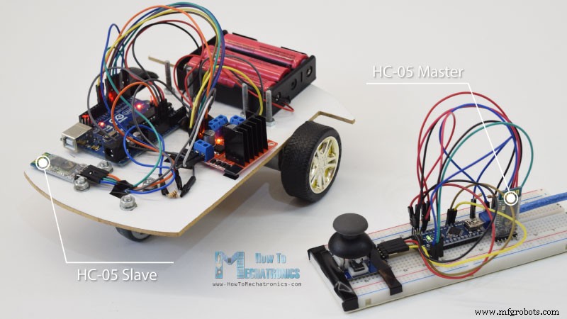
Беспроводное управление автомобилем-роботом Arduino с использованием Bluetooth HC-05, модулей приемопередатчика NRF24L01 и HC-12
<основной класс="главный сайт" id="главный">
В этом уроке мы научимся беспроводному управлению автомобилем-роботом Arduino, который мы сделали в предыдущем видео. Я покажу вам три различных метода беспроводного управления с использованием модуля Bluetooth HC-05, модуля приемопередатчика NRF24L01 и модуля беспроводной связи дальнего радиуса действия HC-12, а также с помощью смартфона и специального приложения для Android. Вы можете посмотреть следующее видео или прочитать письменное руководство ниже для получения более подробной информации.
У меня уже есть руководства по подключению и использованию каждого из этих модулей с платой Arduino, поэтому, если вам нужны дополнительные сведения, вы всегда можете их просмотреть. Ссылки на каждую из них можно найти ниже в статье.
Управление автомобилем-роботом Arduino с помощью Bluetooth-модуля HC-05
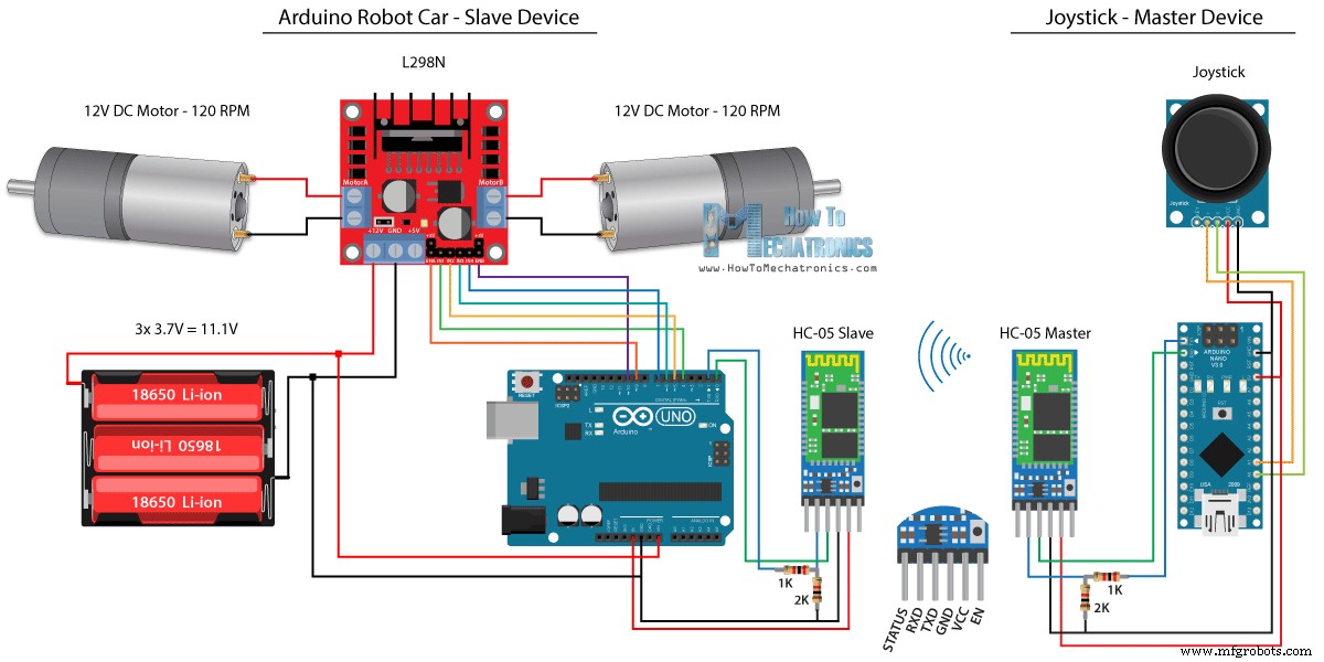
Мы начнем с связи Bluetooth, и для этой цели нам понадобятся два модуля Bluetooth HC-05, которые необходимо настроить как ведущее и ведомое устройства.
Мы можем легко сделать это с помощью AT-команд, и я установил джойстик в качестве ведущего, а автомобиль-робот Arduino — в качестве ведомого. Вот полная схема для этого примера:
Компоненты, необходимые для этого примера, можно получить по ссылкам ниже:
- Модуль Bluetooth HC-05 ………….…
- Модуль джойстика ………………………….
- 18650 Аккумуляторы ……………………………..
- Зарядное устройство 18650…………………
- Драйвер L298N ………………………………..
- Двигатель постоянного тока с высоким крутящим моментом 12 В …………
- Плата Arduino ……………………………
Исходный код
Мы будем использовать тот же код из предыдущего урока, где мы управляем роботизированной машиной Arduino напрямую с помощью джойстика, и внесем в него некоторые изменения.
Мастер-код HC-05:
/*
   Arduino Robot Car Wireless Control using the HC-05 Bluetooth

                == MASTER DEVICE - Joystick ==

   by Dejan Nedelkovski, www.HowToMechatronics.com
*/

int xAxis, yAxis;

void setup() {
  Serial.begin(38400); // Default communication rate of the Bluetooth module
}

void loop() {
  xAxis = analogRead(A0); // Read Joysticks X-axis
  yAxis = analogRead(A1); // Read Joysticks Y-axis

  // Send the values via the serial port to the slave HC-05 Bluetooth device
  Serial.write(xAxis/4); // Dividing by 4 for converting from 0 - 1023 to 0 - 256, (1 byte) range
  Serial.write(yAxis/4);
  delay(20);
}Code language: Arduino (arduino)
Код на ведущем устройстве или джойстике довольно прост. Нам просто нужно прочитать значения X и Y джойстика, которые фактически регулируют скорость двигателей, и отправить их через последовательный порт на ведомое устройство Bluetooth HC-05. Здесь можно отметить, что аналоговые значения джойстика от 0 до 1023 преобразуются в значения от 0 до 255 путем деления их на 4.
Мы делаем это потому, что этот диапазон от 0 до 255 может быть отправлен через устройство Bluetooth в виде 1 байта, который легче принять на другой стороне или в машине-роботе Arduino.
Итак, здесь, если серийный номер получил 2 байта, значения X и Y, с помощью функции Serial.read() мы прочитаем их оба.
// Code from the Arduino Robot Car

// Read the incoming data from the Joystick, or the master Bluetooth device
  while (Serial.available() >= 2) {
    x = Serial.read();
    delay(10);
    y = Serial.read();
  }Code language: Arduino (arduino)
Теперь нам просто нужно преобразовать значения обратно в диапазон от 0 до 1023, подходящий для приведенного ниже кода управления двигателем, принцип работы которого мы уже объяснили в предыдущем видео.
// Code from the Arduino Robot Car

// Convert back the 0 - 255 range to 0 - 1023, suitable for motor control code below
xAxis = x*4;
yAxis = y*4;Code language: Arduino (arduino)
Небольшое замечание:при загрузке кода нам нужно отключить контакты RX и TX платы Arduino.
Полный код подчиненного устройства HC-05:
/*
   Arduino Robot Car Wireless Control using the HC-05 Bluetooth

             == SLAVE DEVICE - Arduino robot car ==

   by Dejan Nedelkovski, www.HowToMechatronics.com
*/

#define enA 9
#define in1 4
#define in2 5
#define enB 10
#define in3 6
#define in4 7

int xAxis, yAxis;
unsigned int  x = 0;
unsigned int  y = 0;

int motorSpeedA = 0;
int motorSpeedB = 0;

void setup() {
  pinMode(enA, OUTPUT);
  pinMode(enB, OUTPUT);
  pinMode(in1, OUTPUT);
  pinMode(in2, OUTPUT);
  pinMode(in3, OUTPUT);
  pinMode(in4, OUTPUT);

  Serial.begin(38400); // Default communication rate of the Bluetooth module
}

void loop() {
  // Default value - no movement when the Joystick stays in the center
  x = 510 / 4;
  y = 510 / 4;

  // Read the incoming data from the Joystick, or the master Bluetooth device
  while (Serial.available() >= 2) {
    x = Serial.read();
    delay(10);
    y = Serial.read();
  }
  delay(10);
  // Convert back the 0 - 255 range to 0 - 1023, suitable for motor control code below
  xAxis = x*4;
  yAxis = y*4;

  // Y-axis used for forward and backward control
  if (yAxis < 470) {
    // Set Motor A backward
    digitalWrite(in1, HIGH);
    digitalWrite(in2, LOW);
    // Set Motor B backward
    digitalWrite(in3, HIGH);
    digitalWrite(in4, LOW);
    // Convert the declining Y-axis readings for going backward from 470 to 0 into 0 to 255 value for the PWM signal for increasing the motor speed
    motorSpeedA = map(yAxis, 470, 0, 0, 255);
    motorSpeedB = map(yAxis, 470, 0, 0, 255);
  }
  else if (yAxis > 550) {
    // Set Motor A forward
    digitalWrite(in1, LOW);
    digitalWrite(in2, HIGH);
    // Set Motor B forward
    digitalWrite(in3, LOW);
    digitalWrite(in4, HIGH);
    // Convert the increasing Y-axis readings for going forward from 550 to 1023 into 0 to 255 value for the PWM signal for increasing the motor speed
    motorSpeedA = map(yAxis, 550, 1023, 0, 255);
    motorSpeedB = map(yAxis, 550, 1023, 0, 255);
  }
  // If joystick stays in middle the motors are not moving
  else {
    motorSpeedA = 0;
    motorSpeedB = 0;
  }

  // X-axis used for left and right control
  if (xAxis < 470) {
    // Convert the declining X-axis readings from 470 to 0 into increasing 0 to 255 value
    int xMapped = map(xAxis, 470, 0, 0, 255);
    // Move to left - decrease left motor speed, increase right motor speed
    motorSpeedA = motorSpeedA - xMapped;
    motorSpeedB = motorSpeedB + xMapped;
    // Confine the range from 0 to 255
    if (motorSpeedA < 0) {
      motorSpeedA = 0;
    }
    if (motorSpeedB > 255) {
      motorSpeedB = 255;
    }
  }
  if (xAxis > 550) {
    // Convert the increasing X-axis readings from 550 to 1023 into 0 to 255 value
    int xMapped = map(xAxis, 550, 1023, 0, 255);
    // Move right - decrease right motor speed, increase left motor speed
    motorSpeedA = motorSpeedA + xMapped;
    motorSpeedB = motorSpeedB - xMapped;
    // Confine the range from 0 to 255
    if (motorSpeedA > 255) {
      motorSpeedA = 255;
    }
    if (motorSpeedB < 0) {
      motorSpeedB = 0;
    }
  }
  // Prevent buzzing at low speeds (Adjust according to your motors. My motors couldn't start moving if PWM value was below value of 70)
  if (motorSpeedA < 70) {
    motorSpeedA = 0;
  }
  if (motorSpeedB < 70) {
    motorSpeedB = 0;
  }
  analogWrite(enA, motorSpeedA); // Send PWM signal to motor A
  analogWrite(enB, motorSpeedB); // Send PWM signal to motor B
}Code language: Arduino (arduino)
Управление роботом Arduino с помощью смартфона и пользовательского приложения для Android
Далее давайте посмотрим, как мы можем управлять нашим автомобилем-роботом Arduino с помощью специального приложения для Android. Принципиальная схема автомобиля-робота точно такая же, как и в предыдущем примере, с режимом Bluetooth HC-05, установленным в качестве ведомого устройства.
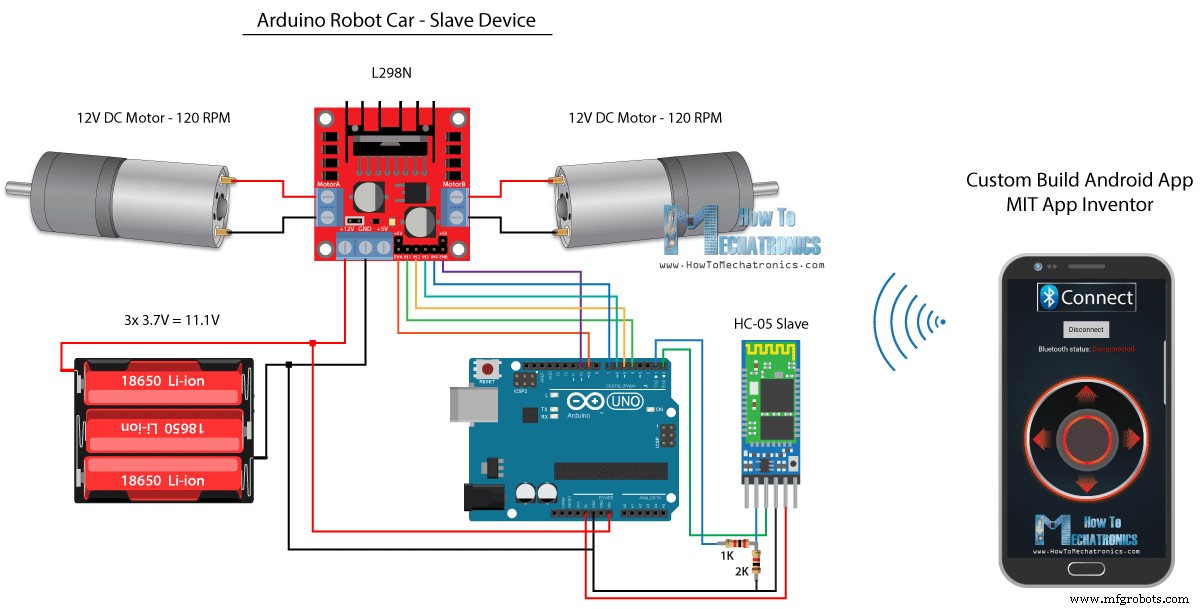
С другой стороны, с помощью онлайн-приложения MIT App Inventor мы создадим собственное приложение для Android, и вот как оно выглядит.
Таким образом, приложение имитирует джойстик, внешний вид которого состоит из двух изображений или спрайтов изображений.
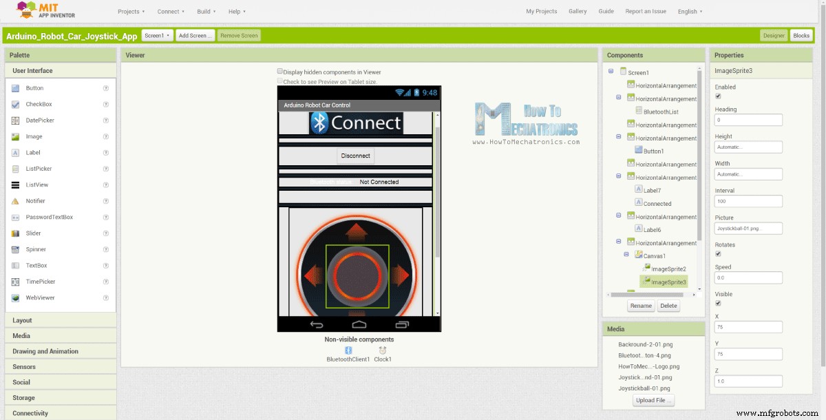
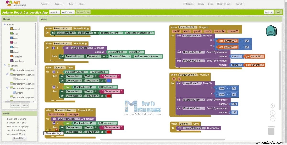
Если мы посмотрим на блоки этого приложения, мы увидим, что при перетаскивании спрайта джойстика изображение шарика джойстика перемещается в текущее положение нашего пальца, и в то же время мы отправляем X и Y значения по Bluetooth в автомобиль Arduino.
Эти значения принимаются Arduino так же, как и в предыдущем примере, с использованием функции Serial.read.
// Read the incoming data from the Smartphone Android App
  while (Serial.available() >= 2) {
    x = Serial.read();
    delay(10);
    y = Serial.read();
  }Code language: Arduino (arduino)
Что нам нужно сделать дополнительно, так это преобразовать полученные значения X и Y со смартфона в диапазон от 0 до 1023, подходящий для приведенного ниже кода управления двигателем. Эти значения зависят от размера холста, а значения X и Y, которые я получал из своего приложения, были от 60 до 220, которые с помощью функции map() я легко преобразовал.
// Makes sure we receive corrent values
  if (x > 60 & x < 220) {
    xAxis = map(x, 220, 60, 1023, 0); // Convert the smartphone X and Y values to 0 - 1023 range, suitable motor for the motor control code below
  }
  if (y > 60 & y < 220) {
    yAxis = map(y, 220, 60, 0, 1023);
  }Code language: Arduino (arduino)
В блоках приложения мы также можем видеть, что когда спрайт изображения ретушируется, шарик джойстика перемещается обратно в центр холста, и соответствующие значения отправляются в автомобиль, чтобы остановить движение. Вы можете найти и загрузить это приложение в статье на веб-сайте, а также два изображения джойстика, чтобы вы могли создать свое собственное или изменить это приложение.
Вы можете скачать приложение для Android ниже, а также два изображения джойстика:

Arduino_Robot_Car_Joystick_App.apk
1 файл(ы) 1,62 МБ Скачать Arduino_Robot_Car_Joystick_App_aia_file
1 файл(ы) 171,20 КБ Скачать Изображения приложения-джойстика
1 файл(ы) 44,36 КБ СкачатьПолный код Arduino:
/*
   Arduino Robot Car Wireless Control using the HC-05 Bluetooth and custom-build Android app

             == SLAVE DEVICE - Arduino robot car ==

   by Dejan Nedelkovski, www.HowToMechatronics.com
*/

#define enA 9
#define in1 4
#define in2 5
#define enB 10
#define in3 6
#define in4 7

int xAxis, yAxis;
int  x = 0;
int  y = 0;

int motorSpeedA = 0;
int motorSpeedB = 0;

void setup() {
  pinMode(enA, OUTPUT);
  pinMode(enB, OUTPUT);
  pinMode(in1, OUTPUT);
  pinMode(in2, OUTPUT);
  pinMode(in3, OUTPUT);
  pinMode(in4, OUTPUT);

  Serial.begin(38400); // Default communication rate of the Bluetooth module
}

void loop() {
  // Default value - no movement when the Joystick stays in the center
  xAxis = 510;
  yAxis = 510;

  // Read the incoming data from the Smartphone Android App
  while (Serial.available() >= 2) {
    x = Serial.read();
    delay(10);
    y = Serial.read();
  }
  delay(10);

  // Makes sure we receive corrent values
  if (x > 60 & x < 220) {
    xAxis = map(x, 220, 60, 1023, 0); // Convert the smartphone X and Y values to 0 - 1023 range, suitable motor for the motor control code below
  }
  if (y > 60 & y < 220) {
    yAxis = map(y, 220, 60, 0, 1023);
  }

  // Y-axis used for forward and backward control
  if (yAxis < 470) {
    // Set Motor A backward
    digitalWrite(in1, HIGH);
    digitalWrite(in2, LOW);
    // Set Motor B backward
    digitalWrite(in3, HIGH);
    digitalWrite(in4, LOW);
    // Convert the declining Y-axis readings for going backward from 470 to 0 into 0 to 255 value for the PWM signal for increasing the motor speed
    motorSpeedA = map(yAxis, 470, 0, 0, 255);
    motorSpeedB = map(yAxis, 470, 0, 0, 255);
  }
  else if (yAxis > 550) {
    // Set Motor A forward
    digitalWrite(in1, LOW);
    digitalWrite(in2, HIGH);
    // Set Motor B forward
    digitalWrite(in3, LOW);
    digitalWrite(in4, HIGH);
    // Convert the increasing Y-axis readings for going forward from 550 to 1023 into 0 to 255 value for the PWM signal for increasing the motor speed
    motorSpeedA = map(yAxis, 550, 1023, 0, 255);
    motorSpeedB = map(yAxis, 550, 1023, 0, 255);
  }
  // If joystick stays in middle the motors are not moving
  else {
    motorSpeedA = 0;
    motorSpeedB = 0;
  }

  // X-axis used for left and right control
  if (xAxis < 470) {
    // Convert the declining X-axis readings from 470 to 0 into increasing 0 to 255 value
    int xMapped = map(xAxis, 470, 0, 0, 255);
    // Move to left - decrease left motor speed, increase right motor speed
    motorSpeedA = motorSpeedA - xMapped;
    motorSpeedB = motorSpeedB + xMapped;
    // Confine the range from 0 to 255
    if (motorSpeedA < 0) {
      motorSpeedA = 0;
    }
    if (motorSpeedB > 255) {
      motorSpeedB = 255;
    }
  }
  if (xAxis > 550) {
    // Convert the increasing X-axis readings from 550 to 1023 into 0 to 255 value
    int xMapped = map(xAxis, 550, 1023, 0, 255);
    // Move right - decrease right motor speed, increase left motor speed
    motorSpeedA = motorSpeedA + xMapped;
    motorSpeedB = motorSpeedB - xMapped;
    // Confine the range from 0 to 255
    if (motorSpeedA > 255) {
      motorSpeedA = 255;
    }
    if (motorSpeedB < 0) {
      motorSpeedB = 0;
    }
  }
  // Prevent buzzing at low speeds (Adjust according to your motors. My motors couldn't start moving if PWM value was below value of 70)
  if (motorSpeedA < 70) {
    motorSpeedA = 0;
  }
  if (motorSpeedB < 70) {
    motorSpeedB = 0;
  }
  analogWrite(enA, motorSpeedA); // Send PWM signal to motor A
  analogWrite(enB, motorSpeedB); // Send PWM signal to motor B
}Code language: Arduino (arduino)
Беспроводное управление роботом-автомобилем Arduino с помощью модуля приемопередатчика NRF24L01
Теперь мы можем перейти к следующему методу, беспроводному управлению автомобилем-роботом Arduino с помощью приемопередающих модулей NRF24L01.
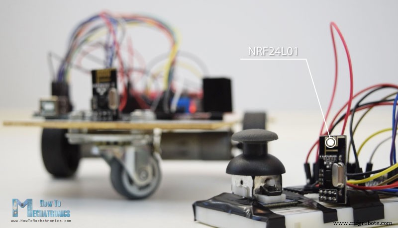
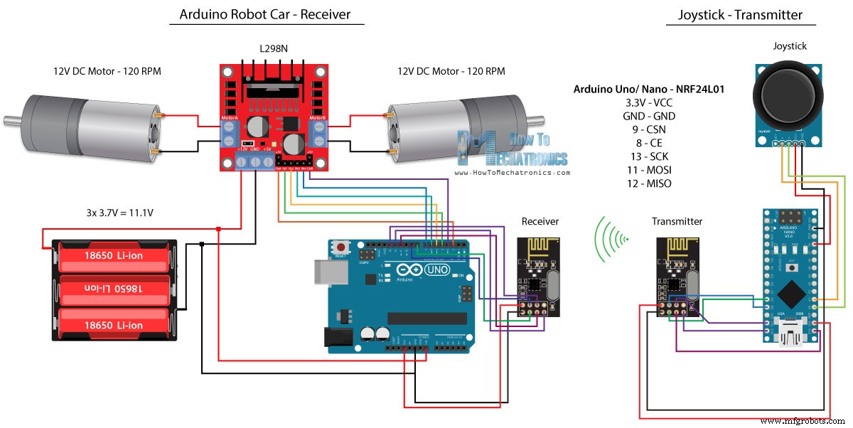
Вот принципиальная схема. Мы можем отметить, что эти модули используют связь SPI, поэтому по сравнению с предыдущим примером я переместил контакты Enable A и Enable B драйвера L298N на контакты 2 и 3 платы Arduino. Вы можете получить NRF24L01. модуль по следующей ссылке Amazon.
Исходный код
Для этого примера нам нужно установить библиотеку RF24. Как и в предыдущем примере, после определения некоторых выводов и настройки модуля в качестве передатчика мы считываем значения X и Y джойстика и отправляем их другому модулю NRF24L01 в машине-роботе Arduino.
Во-первых, можно отметить, что аналоговые показания представляют собой строки, которые с помощью функции string.toCharArray() помещаются в массив символов. Затем с помощью функции radio.write() мы отправляем данные этого массива символов в другой модуль.
Код передатчика:
/*
   Arduino Robot Car Wireless Control using the NRF24L01 Transceiver module

             == Transmitter - Joystick ==

   by Dejan Nedelkovski, www.HowToMechatronics.com

   Library: TMRh20/RF24, https://github.com/tmrh20/RF24/
*/

#include <SPI.h>
#include <nRF24L01.h>
#include <RF24.h>

RF24 radio(8, 9); // CE, CSN
const byte address[6] = "00001";

char xyData[32] = "";
String xAxis, yAxis;

void setup() {
  Serial.begin(9600);
  radio.begin();
  radio.openWritingPipe(address);
  radio.setPALevel(RF24_PA_MIN);
  radio.stopListening();
}

void loop() {

  xAxis = analogRead(A0); // Read Joysticks X-axis
  yAxis = analogRead(A1); // Read Joysticks Y-axis
  // X value
  xAxis.toCharArray(xyData, 5); // Put the String (X Value) into a character array
  radio.write(&xyData, sizeof(xyData)); // Send the array data (X value) to the other NRF24L01 modile
  // Y value
  yAxis.toCharArray(xyData, 5);
  radio.write(&xyData, sizeof(xyData));
  delay(20);
}Code language: Arduino (arduino)
С другой стороны. в автомобиле робота Arduino, после определения модуля в качестве приемника, мы принимаем данные с помощью функции radio.read(). Затем с помощью функции atoi() мы преобразуем полученные данные или значения X и Y с джойстика в целочисленные значения, которые подходят для приведенного ниже кода управления двигателем.
// Code from the Arduino Robot Car - NRF24L01 example

if (radio.available()) {   // If the NRF240L01 module received data
    radio.read(&receivedData, sizeof(receivedData)); // Read the data and put it into character array
    xAxis = atoi(&receivedData[0]); // Convert the data from the character array (received X value) into integer
    delay(10);
    radio.read(&receivedData, sizeof(receivedData));
    yAxis = atoi(&receivedData[0]);
    delay(10);
  }Code language: Arduino (arduino)
Это так просто, но, конечно, как я уже сказал, если вам нужна дополнительная информация о том, как подключить и настроить модули, вы всегда можете проверить это в моем конкретном руководстве.
Код получателя:
/*
   Arduino Robot Car Wireless Control using the NRF24L01 Transceiver module

             == Receiver - Arduino robot car ==

   by Dejan Nedelkovski, www.HowToMechatronics.com

   Library: TMRh20/RF24, https://github.com/tmrh20/RF24/
*/
#include <SPI.h>
#include <nRF24L01.h>
#include <RF24.h>

#define enA 2   // Note: Pin 9 in previous video ( pin 10 is used for the SPI communication of the NRF24L01)
#define in1 4
#define in2 5
#define enB 3   // Note:  Pin 10 in previous video
#define in3 6
#define in4 7

RF24 radio(8, 9); // CE, CSN
const byte address[6] = "00001";

char receivedData[32] = "";
int  xAxis, yAxis;

int motorSpeedA = 0;
int motorSpeedB = 0;

void setup() {
  pinMode(enA, OUTPUT);
  pinMode(enB, OUTPUT);
  pinMode(in1, OUTPUT);
  pinMode(in2, OUTPUT);
  pinMode(in3, OUTPUT);
  pinMode(in4, OUTPUT);
  Serial.begin(9600);
  radio.begin();
  radio.openReadingPipe(0, address);
  radio.setPALevel(RF24_PA_MIN);
  radio.startListening();
}

void loop() {

  if (radio.available()) {   // If the NRF240L01 module received data
    radio.read(&receivedData, sizeof(receivedData)); // Read the data and put it into character array
    xAxis = atoi(&receivedData[0]); // Convert the data from the character array (received X value) into integer
    delay(10);
    radio.read(&receivedData, sizeof(receivedData));
    yAxis = atoi(&receivedData[0]);
    delay(10);
  }

  // Y-axis used for forward and backward control
  if (yAxis < 470) {
    // Set Motor A backward
    digitalWrite(in1, HIGH);
    digitalWrite(in2, LOW);
    // Set Motor B backward
    digitalWrite(in3, HIGH);
    digitalWrite(in4, LOW);
    // Convert the declining Y-axis readings for going backward from 470 to 0 into 0 to 255 value for the PWM signal for increasing the motor speed
    motorSpeedA = map(yAxis, 470, 0, 0, 255);
    motorSpeedB = map(yAxis, 470, 0, 0, 255);
  }
  else if (yAxis > 550) {
    // Set Motor A forward
    digitalWrite(in1, LOW);
    digitalWrite(in2, HIGH);
    // Set Motor B forward
    digitalWrite(in3, LOW);
    digitalWrite(in4, HIGH);
    // Convert the increasing Y-axis readings for going forward from 550 to 1023 into 0 to 255 value for the PWM signal for increasing the motor speed
    motorSpeedA = map(yAxis, 550, 1023, 0, 255);
    motorSpeedB = map(yAxis, 550, 1023, 0, 255);
  }
  // If joystick stays in middle the motors are not moving
  else {
    motorSpeedA = 0;
    motorSpeedB = 0;
  }

  // X-axis used for left and right control
  if (xAxis < 470) {
    // Convert the declining X-axis readings from 470 to 0 into increasing 0 to 255 value
    int xMapped = map(xAxis, 470, 0, 0, 255);
    // Move to left - decrease left motor speed, increase right motor speed
    motorSpeedA = motorSpeedA - xMapped;
    motorSpeedB = motorSpeedB + xMapped;
    // Confine the range from 0 to 255
    if (motorSpeedA < 0) {
      motorSpeedA = 0;
    }
    if (motorSpeedB > 255) {
      motorSpeedB = 255;
    }
  }
  if (xAxis > 550) {
    // Convert the increasing X-axis readings from 550 to 1023 into 0 to 255 value
    int xMapped = map(xAxis, 550, 1023, 0, 255);
    // Move right - decrease right motor speed, increase left motor speed
    motorSpeedA = motorSpeedA + xMapped;
    motorSpeedB = motorSpeedB - xMapped;
    // Confine the range from 0 to 255
    if (motorSpeedA > 255) {
      motorSpeedA = 255;
    }
    if (motorSpeedB < 0) {
      motorSpeedB = 0;
    }
  }
  // Prevent buzzing at low speeds (Adjust according to your motors. My motors couldn't start moving if PWM value was below value of 70)
  if (motorSpeedA < 70) {
    motorSpeedA = 0;
  }
  if (motorSpeedB < 70) {
    motorSpeedB = 0;
  }
  analogWrite(enA, motorSpeedA); // Send PWM signal to motor A
  analogWrite(enB, motorSpeedB); // Send PWM signal to motor B
}Code language: Arduino (arduino)
Беспроводное управление роботом Arduino с помощью приемопередатчика дальнего действия HC-12
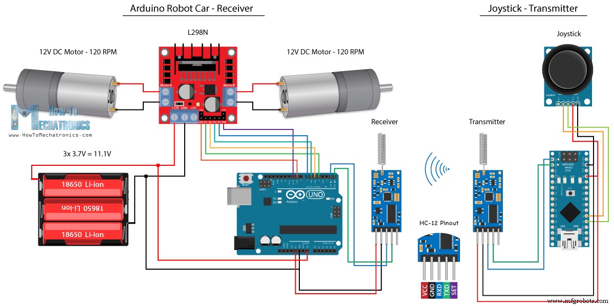
Для последнего метода беспроводного управления автомобилем-роботом Arduino мы будем использовать модули приемопередатчика дальнего действия HC-12. Эти модули могут связываться друг с другом на расстоянии до 1,8 км.
Схема для этого примера почти такая же, как и для модулей Bluetooth HC-05, поскольку они используют тот же метод для связи с Arduino через последовательный порт.
Вы можете получить модуль приемопередатчика HC-12 по следующей ссылке Amazon.
Исходный код
Код джойстика точно такой же, как и для связи Bluetooth. Мы просто считываем аналоговые значения джойстика и отправляем их в другой модуль с помощью функции Serial.write().
Код передатчика:
/*
   Arduino Robot Car Wireless Control using the HC-12 long range wireless module

                == Transmitter - Joystick ==

   by Dejan Nedelkovski, www.HowToMechatronics.com
*/

int xAxis, yAxis;

void setup() {
  Serial.begin(9600); // Default communication rate of the Bluetooth module
}

void loop() {
  xAxis = analogRead(A0); // Read Joysticks X-axis
  yAxis = analogRead(A1); // Read Joysticks Y-axis

  // Send the values via the serial port to the slave HC-05 Bluetooth device
  Serial.write(xAxis/4); // Dividing by 4 for converting from 0 - 1023 to 0 - 256, (1 byte) range
  Serial.write(yAxis/4);
  delay(20);
}Code language: Arduino (arduino)
С другой стороны, в цикле while() мы ждем поступления данных, затем считываем их с помощью функции Serial.read() и преобразуем обратно в диапазон от 0 до 1023, подходящий для приведенного ниже кода управления двигателем.
Код получателя:
/*
   Arduino Robot Car Wireless Control using the HC-12 long range wireless module

             == Receiver - Arduino robot car ==

   by Dejan Nedelkovski, www.HowToMechatronics.com
*/

#define enA 9
#define in1 4
#define in2 5
#define enB 10
#define in3 6
#define in4 7

int xAxis, yAxis;
int  x = 0;
int  y = 0;

int motorSpeedA = 0;
int motorSpeedB = 0;

void setup() {
  pinMode(enA, OUTPUT);
  pinMode(enB, OUTPUT);
  pinMode(in1, OUTPUT);
  pinMode(in2, OUTPUT);
  pinMode(in3, OUTPUT);
  pinMode(in4, OUTPUT);

  Serial.begin(9600); // Default communication rate of the Bluetooth module
}

void loop() {
  // Default value - no movement when the Joystick stays in the center
  xAxis = 510;
  yAxis = 510;

  // Read the incoming data from the
  while (Serial.available() == 0) {}
  x = Serial.read();
  delay(10);
  y = Serial.read();
  delay(10);

  // Convert back the 0 - 255 range to 0 - 1023, suitable for motor control code below
  xAxis = x * 4;
  yAxis = y * 4;

  // Y-axis used for forward and backward control
  if (yAxis < 470) {
    // Set Motor A backward
    digitalWrite(in1, HIGH);
    digitalWrite(in2, LOW);
    // Set Motor B backward
    digitalWrite(in3, HIGH);
    digitalWrite(in4, LOW);
    // Convert the declining Y-axis readings for going backward from 470 to 0 into 0 to 255 value for the PWM signal for increasing the motor speed
    motorSpeedA = map(yAxis, 470, 0, 0, 255);
    motorSpeedB = map(yAxis, 470, 0, 0, 255);
  }
  else if (yAxis > 550) {
    // Set Motor A forward
    digitalWrite(in1, LOW);
    digitalWrite(in2, HIGH);
    // Set Motor B forward
    digitalWrite(in3, LOW);
    digitalWrite(in4, HIGH);
    // Convert the increasing Y-axis readings for going forward from 550 to 1023 into 0 to 255 value for the PWM signal for increasing the motor speed
    motorSpeedA = map(yAxis, 550, 1023, 0, 255);
    motorSpeedB = map(yAxis, 550, 1023, 0, 255);
  }
  // If joystick stays in middle the motors are not moving
  else {
    motorSpeedA = 0;
    motorSpeedB = 0;
  }

  // X-axis used for left and right control
  if (xAxis < 470) {
    // Convert the declining X-axis readings from 470 to 0 into increasing 0 to 255 value
    int xMapped = map(xAxis, 470, 0, 0, 255);
    // Move to left - decrease left motor speed, increase right motor speed
    motorSpeedA = motorSpeedA - xMapped;
    motorSpeedB = motorSpeedB + xMapped;
    // Confine the range from 0 to 255
    if (motorSpeedA < 0) {
      motorSpeedA = 0;
    }
    if (motorSpeedB > 255) {
      motorSpeedB = 255;
    }
  }
  if (xAxis > 550) {
    // Convert the increasing X-axis readings from 550 to 1023 into 0 to 255 value
    int xMapped = map(xAxis, 550, 1023, 0, 255);
    // Move right - decrease right motor speed, increase left motor speed
    motorSpeedA = motorSpeedA + xMapped;
    motorSpeedB = motorSpeedB - xMapped;
    // Confine the range from 0 to 255
    if (motorSpeedA > 255) {
      motorSpeedA = 255;
    }
    if (motorSpeedB < 0) {
      motorSpeedB = 0;
    }
  }
  // Prevent buzzing at low speeds (Adjust according to your motors. My motors couldn't start moving if PWM value was below value of 70)
  if (motorSpeedA < 70) {
    motorSpeedA = 0;
  }
  if (motorSpeedB < 70) {
    motorSpeedB = 0;
  }
  analogWrite(enA, motorSpeedA); // Send PWM signal to motor A
  analogWrite(enB, motorSpeedB); // Send PWM signal to motor B
}Code language: Arduino (arduino)
Так что это почти все для этого урока. Не стесняйтесь задавать любые вопросы в разделе комментариев ниже.
Производственный процесс
- Робот Raspberry Pi, управляемый через Bluetooth
- Универсальный пульт дистанционного управления с использованием Arduino, 1Sheeld и Android
- Вольтметр своими руками с использованием Arduino и смартфона
- Arduino с Bluetooth для управления светодиодом!
- Управление Arduino Rover с помощью Firmata и контроллера Xbox One
- Счетчик автомобилей с использованием Arduino + Обработка + PHP
- Полный контроль над вашим телевизором с помощью Alexa и Arduino IoT Cloud
- FM-радио с использованием Arduino и RDA8057M
- BLUE_P:беспроводной экран программирования Arduino
- Управление автомобилем с помощью Arduino Uno и Bluetooth