


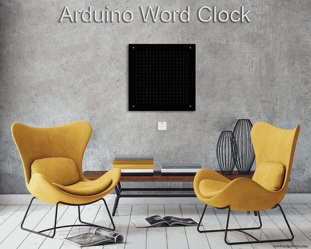
Word Clock с минутным разрешением времени в словах
Компоненты и расходные материалы
 |
| × | 1 |
Об этом проекте
Более подробную информацию об этой сборке можно найти на моем сайте здесь:Word Clock
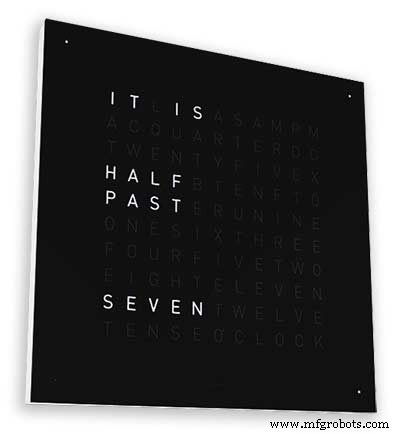
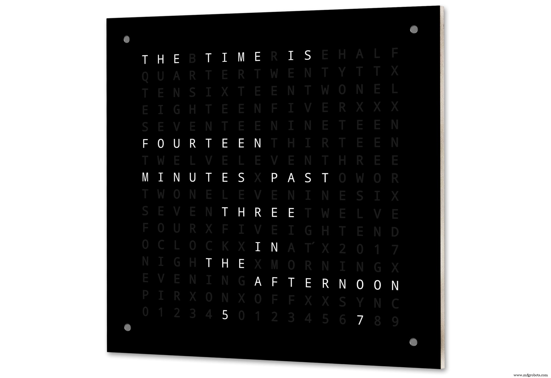
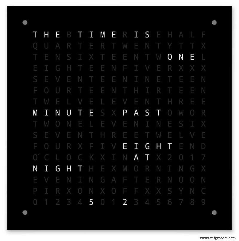
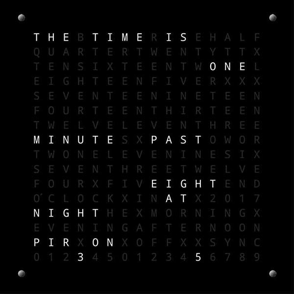
Словарные часы Arduino с минутным разрешением времени в словах и линейным отображением секунд.
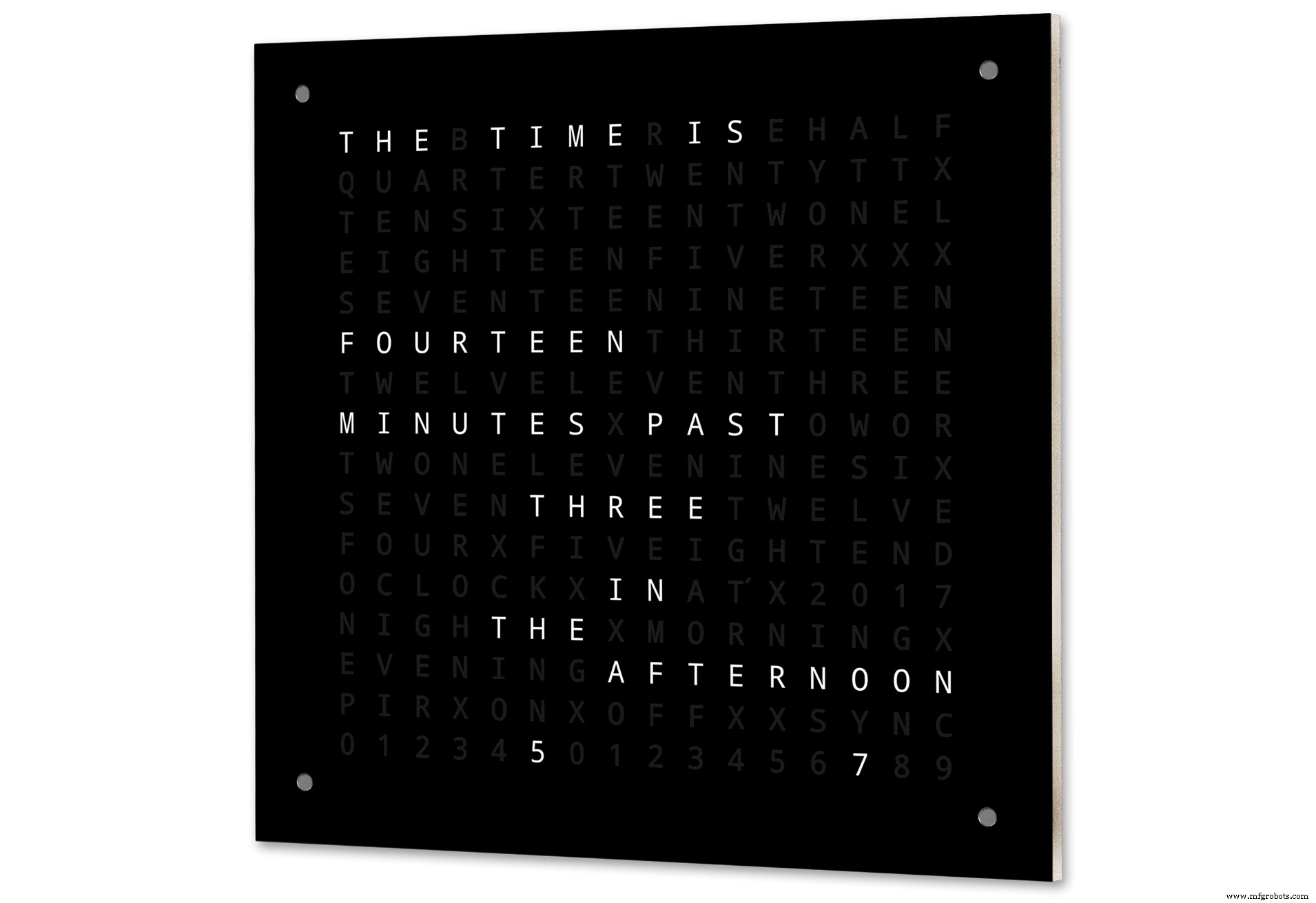
Также есть режимы для цифровых часов, аналоговых часов, температуры и влажности, а также три игры:Game of Life, Simon и Tetris.
Часы могут быть автономными или работать в качестве ведомого устройства от главных часов, если это необходимо.
Без главных часов время контролируется встроенными часами реального времени с температурной компенсацией.
Существует возможность управления ИК-датчиком или доплеровским радаром, поэтому часы автоматически отключаются, когда в комнате никого нет.
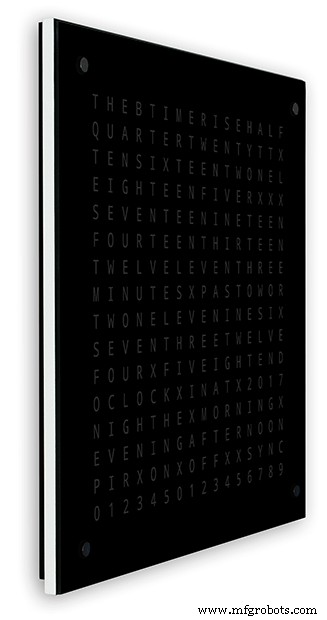
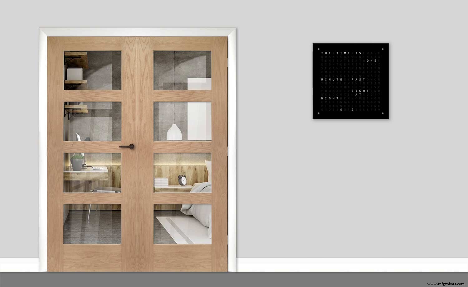
Часы имеют размеры 500 x 500 мм (19,68 x 19,68 дюйма), вес 12 фунтов (5,5 кг) и предназначены для настенного монтажа. В каждом углу есть сенсорные панели для настройки часов и управления ими.
Шаг 1. О Word Clocks
О Word Clocks
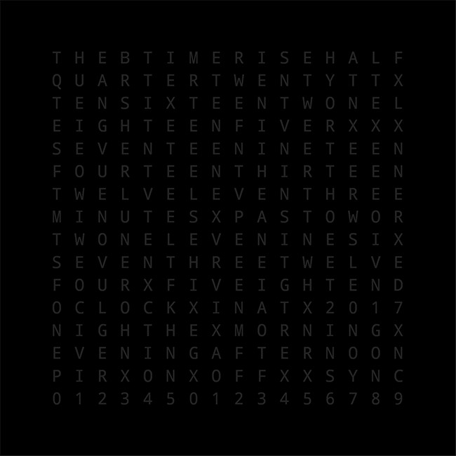
Словесные часы показывают время, используя матрицу слов или цифр и букв, и существуют уже много лет. Есть несколько различных типов дизайна, которые влияют на сложность сборки часов.
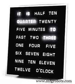
Простейшие блоки слов используются для определения времени с пятиминутным разрешением, например, O'CLOCK, 5 PAST, 10 PAST и т. Д. Эти часы используют только 20 или около того отдельных светодиодных блоков, и поэтому их проще всего построить. Основным недостатком этих часов является то, что они могут показывать время только в заданном формате.
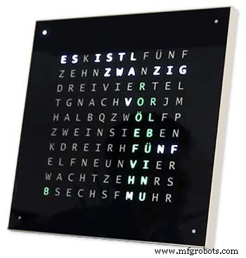
Часы среднего уровня имеют матрицу светодиодов 11x10 плюс четыре дополнительных светодиода вокруг часов. Часы, управляемые Raspberry Pi, Photo 2 даже имеют многоцветные светодиоды, а поскольку они имеют 110 отдельных светодиодов, они могут отображать цифры и базовые изображения. Эти часы по-прежнему используют 5-минутное разрешение в словах, но часто добавляют «только что прошло 5 минут» или почти 10, чтобы немного увеличить разрешение. Часто четыре светодиода по углам рамки показывают прошедшие четыре минуты, чтобы заполнить промежуток между 5-минутное разрешение. Эти часы достаточно сложны в изготовлении, и для облегчения сборки часто используются полосы светодиодов.
Доступны коммерческие версии часов этого типа. Настенная версия 450 мм стоит около 1000 фунтов стерлингов и имеет сменные передние панели разных цветов и материалов, а также доступны настольный компьютер и часы меньшего размера.
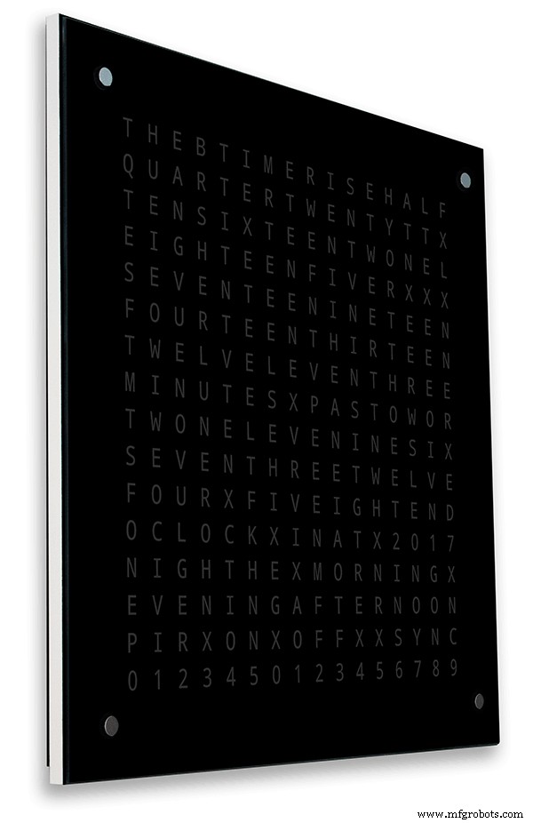
256-матричные Word Clock от Воутера Девинка
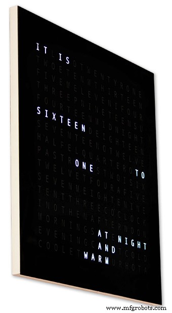
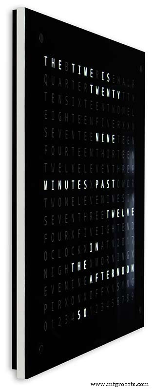
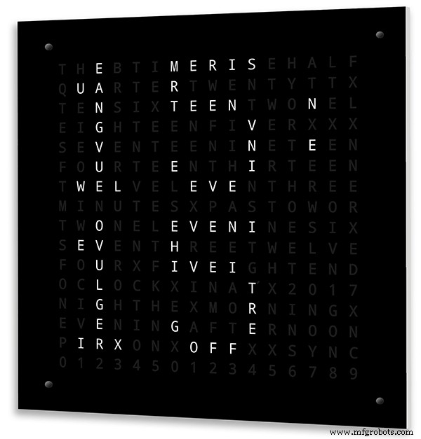
В словарных часах самого высокого уровня сложности используется светодиодная матрица 16x16, обеспечивающая управление целыми 256 светодиодами. Эти часы имеют разрешение времени в одну минуту, а также время утра, вечера, ночи и т. Д. Они часто выражают приблизительную температуру словами. например, тепло, очень тепло, холодно, очень холодно и т. д.
С 256 светодиодами доступно огромное количество различных режимов отображения. Эти часы довольно сложно построить из-за большого количества подключений в матричном дисплее. Построение светодиодной матрицы на печатных платах с компонентами для поверхностного монтажа позволяет создавать очень тонкие корпуса часов и упрощает конструкцию дисплея, но более 500 мм x 500 мм печатные платы начинают становиться дорогими.
Для ручной сборки светодиодной матрицы, как в моих часах, требуется место, и 500 мм x 500 мм - хорошая отправная точка, поскольку она может примерно вместить большие жгуты проводов, необходимые для соединения светодиодов и модулей дисплея. Настенные наполняющие часы очень большого размера могут быть изготовлены с использованием светодиодных матриц ручной сборки.
Шаг 2. Изменения
Изменения
Эти часы представляют собой смесь аппаратного обеспечения Wouter Devinck Clock и программного обеспечения "Catalan" Pijuana. Я не использовал никаких печатных плат, просто готовые модули и три небольшие схемы платы Vero для питания.
Основные изменения подробно описаны ниже.
В этой версии часов не используются никакие специальные печатные платы, просто доступны дешевые готовые модули.
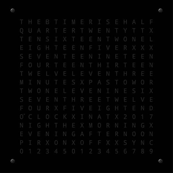
Основной корпус часов состоит из двух листов МДФ толщиной 14 мм, а не из одного листа толщиной 18 мм.
Задний лист на 10 мм меньше переднего со всех сторон, кроме верхней, поэтому толщина часов составляет всего 14 мм.
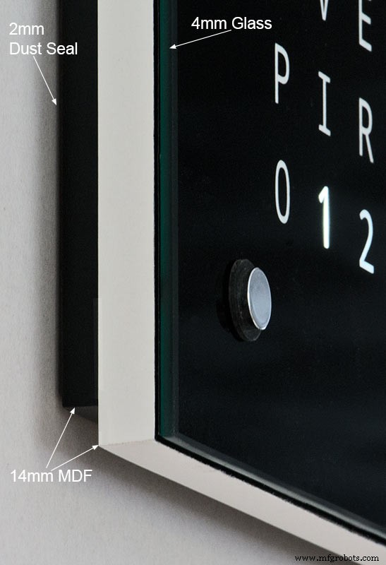
Часы Wouter Devinck имеют глубину всего 20 мм, включая 2-миллиметровое стекло, тогда как мои часы на самом деле имеют глубину 34 мм, включая 4-миллиметровое стекло и 2-миллиметровый пылезащитный уплотнитель на задней панели. Из-за смещения задней 14-миллиметровой панели и 1,5-миллиметрового смещения стеклянной панели под большинством углов часы выглядят только на 14 мм глубиной. Эта дополнительная глубина позволила мне использовать светодиодную матрицу и электрические станки ручной сборки, а не 4 большие печатные платы. Это также означает, что я могу использовать готовые удобные в обслуживании модули без ИС для поверхностного монтажа на платах MAX7219.
Главный дисплей встроен непосредственно в светодиоды дисплея без печатной платы, поэтому возможен дисплей любого размера. Модули сенсорных датчиков TTP223 используются вместо Azoteq IQS127D, установленных на основных платах.
Платы драйвера дисплея для MAX7219 I / C используют модифицированные платы светодиодной матрицы. Эти платы идут в комплекте со всеми компонентами.
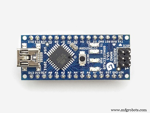
Arduino Nano используется для управления часами из-за своего небольшого размера.
Модуль датчика PIR используется для отключения дисплея, когда в комнате никого нет (это можно отключить, чтобы дисплей оставался всегда включенным).
В схему добавлен подстроечный резистор, доступный снизу часов с помощью небольшой отвертки с плоским лезвием для калибровки автоматической яркости дисплея.
Синхронизация с моей главной системой часов каждую минуту по 30 секунд. Если синхронизирующий импульс недоступен, часы будут работать свободно, используя RTC. Импульсы синхронизации отображаются на главном дисплее.
Программное обеспечение в основном основано на "каталонской" пихуанской версии словарных часов, поэтому для отображения она переведена на английский язык. Отображение кредитов изменено по сравнению с версией "Catalan" Pijuana ", чтобы показать номер текущей версии программного обеспечения, мое имя, а также год сборки.
Указанная температура была удалена с дисплея часов, а линейная индикация секунд добавлена в нижний ряд Word, цифровых и аналоговых часов.
Когда PIR включен или выключен, на дисплее часов отображается несколько секунд «PIR ON» или «PIR OFF».
В этих часах используется прецизионный модуль часов реального времени DS3231 AT24C32 I2C, соответствующий часам Wouter Devinck и «каталонским» часам Pijuana. Я не очень люблю использовать литий-ионную аккумуляторную батарею, поставляемую с модулем. Я использую неперезаряжаемую батарею и модифицировал модуль в соответствии с требованиями.
4-миллиметровое флоат-стекло с полированными краями заменяет 2-миллиметровое стекло. Стекло крепится к основной плите МДФ с помощью крепежа Chicago Fasteners, а не клея. Они также действуют как сенсорные панели для управления часами и позволяют при необходимости снимать стекло.
В часы встроены два пылезащитных уплотнения:один на задней панели, а другой за съемной стеклянной панелью дисплея. В режиме настройки часов нажатие правой кнопки BOT сбрасывает секунды на 0.
Следующие изменения были внесены в английскую формулировку, чтобы сделать формулировку такой, как я бы сказал. То, как люди говорят, что время будет варьироваться от региона к региону, в зависимости от того, где вы живете / ходили в школу и т.д.
Убраны слова, обозначающие температуру на словарных часах. Они были заменены статусом синхронизации, включением / выключением ИК-датчика и линейным отображением секунд.
"МИНУТЫ" заменены на "МИНУТЫ" через 1 минуту и 1 минуту на час.
Добавлена буква "A" перед прошедшим "QUARTER" и "QUARTER" к часу.
Добавлены отсутствующие «ОДИННАДЦАТЬ» с часов Воутера Девинка в соответствии с его примечаниями.
В полдень изменил время на ДВЕНАДЦАТЬ ЧАСОВ В ДНЕ.
В полночь изменили время на ДВЕНАДЦАТЬ ЧАСОВ НОЧИ. После полуночи часы всегда будут говорить «УТРОМ».
"ЧАСЫ" теперь без пунктуации и просто показывают ЧАСЫ.
Шаг 3. Дизайн корпуса
Поскольку в моих часах не используются специальные печатные платы матрицы дисплея с компонентами для поверхностного монтажа, мой корпус часов должен быть несколько глубже, чем конструкция Воутера.
Мой корпус имеет глубину 34 мм и включает в себя задний пылезащитный уплотнитель 2 мм, заднюю панель из МДФ 14 мм, переднюю панель дисплея 14 мм и 4 мм флоат-стекло.
В случае с Воутером глубина всего 21 мм, одинарная панель из МДФ 18 мм и листовое стекло толщиной 2 мм.
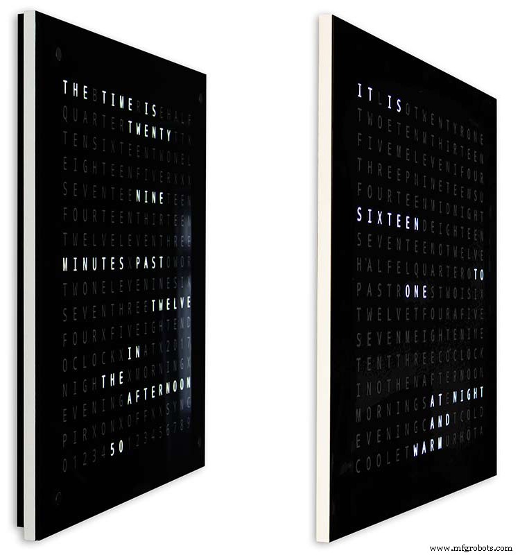
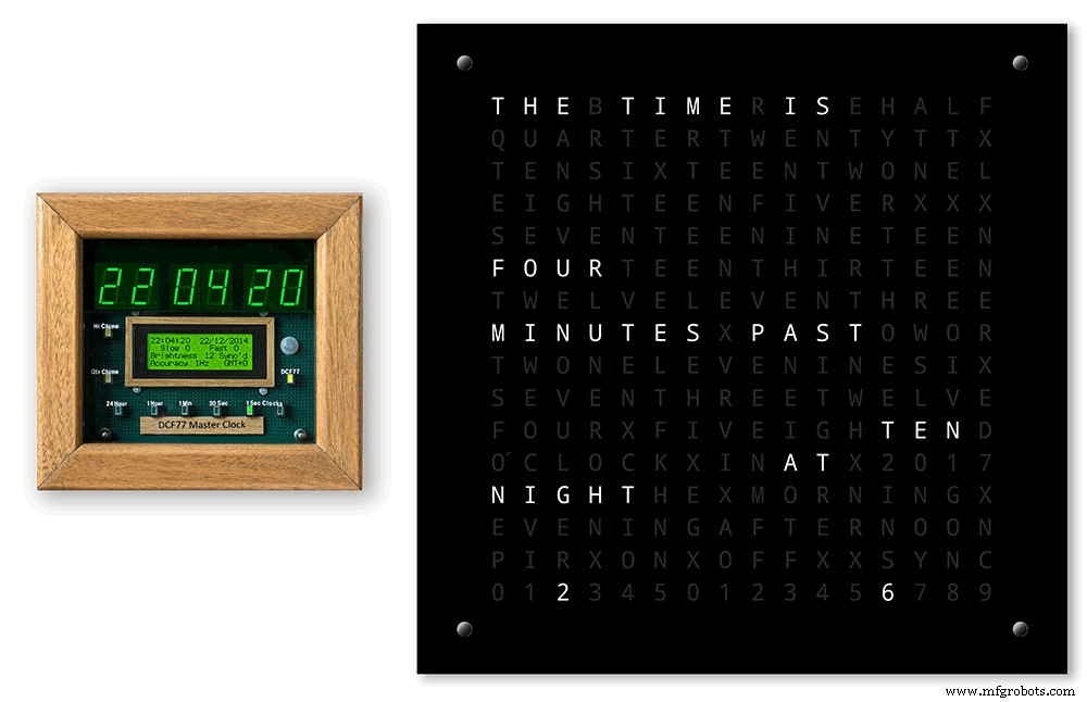
Чтобы часы казались менее громоздкими при установке на стене, я добавил несколько простых конструктивных элементов. На рисунке выше показаны мои часы слева и часы Воутера справа. Если смотреть с крайнего бокового угла, видно, что мой корпус выглядит более громоздким.
Это несколько компенсируется тем, что задняя панель имеет черный цвет, а не белый, поэтому ваш взгляд будет сосредоточен на тонкой белой 14-миллиметровой кромке. Задняя панель на 10 мм короче снизу и с обеих сторон усиливает эту иллюзию.
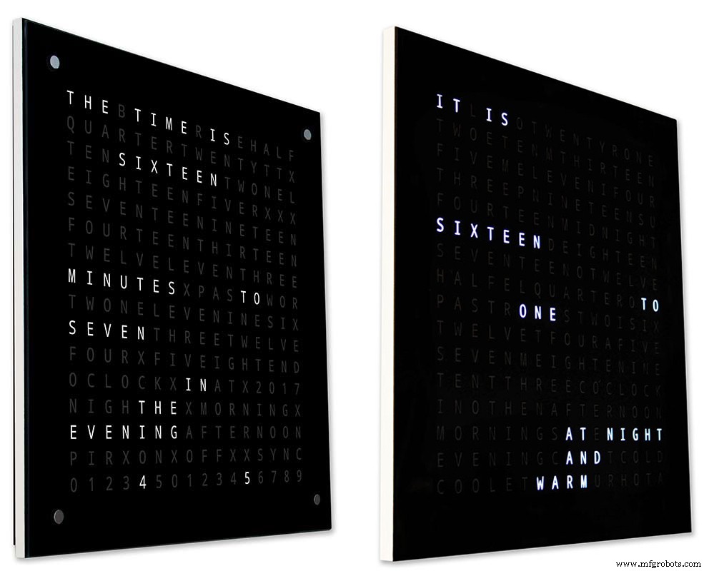
Вверху - снова мои часы слева и часы Воутера справа. Чем дальше вы продвигаетесь к передней части часов, тем короче задняя панель на моих часах исчезает из поля зрения, пока не станет видна только тонкая 14-миллиметровая передняя панель. 4-миллиметровое стекло также на 1-2 мм короче передней панели, что позволяет скрыть его из поля зрения. . Мой громоздкий 34-миллиметровый корпус для часов теперь кажется таким же тонким, как и корпус Воутера.
Шаг 4. Элементы управления
Элементы управления

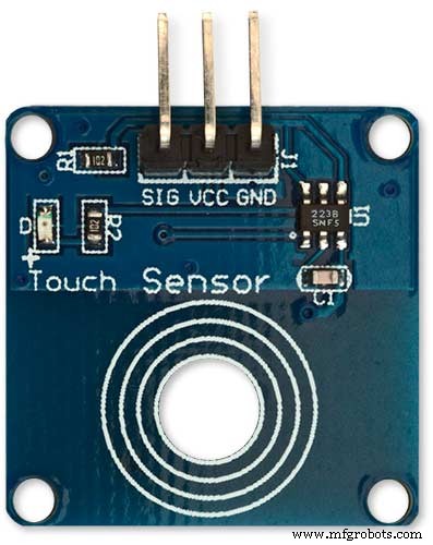
Модули сенсорного управления TTP223 расположены на часах, в верхнем левом, верхнем правом, нижнем левом и нижнем правом углах дисплея.
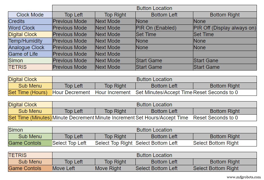
Кнопки выполняют разные функции в зависимости от того, в каком режиме находятся часы, см. Таблицу выше.
Шаг 5. Автоматическая настройка «Лето - Зима»
Не используется.
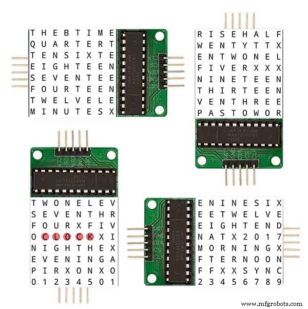
Шаг 6. Режимы отображения, часы и окружающая среда
На анимации 1 выше показаны 4 режима часов и среды.
Доступны следующие режимы:часы со словом, цифровые часы, температура и влажность, а также аналоговые часы.
Анимация 2 выше. Существует также режим запуска, в котором прокручивается номер версии программного обеспечения, имя производителя и название часов.
Шаг 7. Отображение режимов игры
В часах закодированы три классические игры. Я оставил код каталонских часов без изменений.

Анимация 1 выше «Игры жизни» Конвея. Вселенная Игры Жизни представляет собой бесконечную двумерную ортогональную сетку квадратных ячеек, каждая из которых находится в одном из двух возможных состояний:живая или мертвая, или «заселенная» или «незаселенная».
Каждая ячейка взаимодействует со своими восемью соседями, которые являются ячейками, смежными по горизонтали, вертикали или диагонали. На каждом временном шаге происходят следующие переходы:любая живая клетка с менее чем двумя живыми соседями умирает, как если бы это было вызвано недостаточным населением. Любая живая клетка с двумя или тремя живыми соседями доживает до следующего поколения. Любая живая клетка с более чем тремя живыми соседями умирает, как будто от перенаселения. Любая мертвая клетка с ровно тремя живыми соседями становится живой клеткой, как будто в результате размножения.
Первоначальный образец составляет зерно системы. Первое поколение создается путем применения вышеуказанных правил одновременно к каждой ячейке семени, когда рождение и смерть происходят одновременно, и дискретный момент, в который это происходит, иногда называют тиканием (другими словами, каждое поколение является чистой функцией предыдущего. один). Правила продолжают многократно применяться для создания следующих поколений.
Анимация 2 над Саймоном
Игра памяти Саймона - попробуйте скопировать последовательность, сгенерированную компьютером. При вводе последовательности дважды коснитесь последней записи, чтобы завершить ход.
Когда вы проигрываете, ваш результат отображается на экране.
Анимация 3 над Тетрисом Тетрис - советская видеоигра-головоломка с сопоставлением плиток, выпущенная в июне 1984 года. В этой игре все еще нужно доработать кнопки, чтобы правильно управлять плитками.
Шаг 8:прототипирование
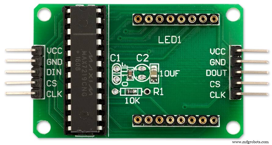
Часы можно прототипировать и протестировать с использованием оригинальных матричных светодиодов DOT на платах дисплея MAX7219.
Обратите внимание, что эта временная модификация требуется только в том случае, если вы хотите протестировать свой код на матричных дисплеях DOT, поставляемых с модулями MAX7219.
Это означает, что вы можете опробовать в миниатюре модификации своего программного обеспечения / макета слов, прежде чем переходить к полноразмерной версии. Проводка к светодиоду DOT Matrix должна быть изменена в соответствии с подключениями программного обеспечения.
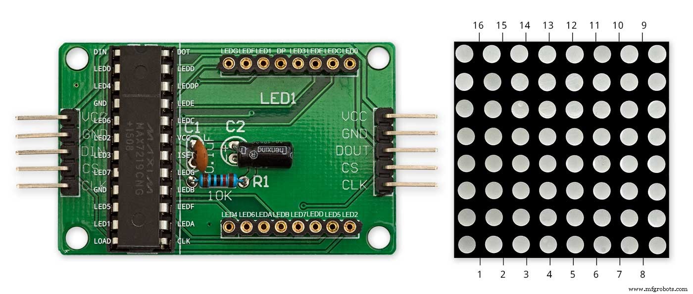
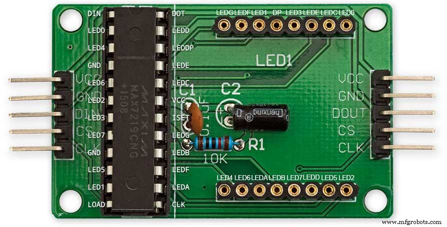
На рис. Выше показано, как модуль подключен перед модификацией. Модификация довольно проста. Прежде всего, согните следующие штыри LED Matrix на 90 °, верхние штыри вверх, а нижние штыри вниз.
Контакты 16, 15, 3, 4, 10 и 11.
Вставьте светодиодную матрицу в гнездо на плате дисплея, указанные выше контакты теперь не будут подключены. Припаяйте следующие соединительные провода от задней части разъема печатной платы дисплея к торчащим контактам матрицы светодиодов.
LEDA к контакту 16 точечной матрицы
LEDB к контакту 15 точечной матрицы
LEDG к контакту 3 точечной матрицы
LEDF к контакту 4 точечной матрицы
LEDE к контакту 10 точечной матрицы
LEDC к контакту 11 точечной матрицы
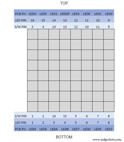
Я использовал мультиметр и отключил дисплейный модуль. В таблице показано, где номер контакта программного обеспечения отличается от номера контакта светодиодного индикатора на плате дисплея.
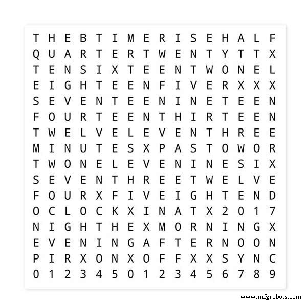
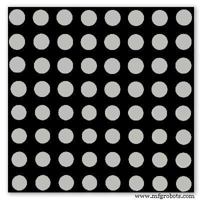
Чтобы проверить макет Word, распечатайте уменьшенную версию дисплея Word 62 мм x 62 мм на простой белой бумаге.
Обратите внимание на ориентацию плат светодиодных дисплеев в соответствии с макетом программного обеспечения.
Я сохранил вращение дисплея как оригинальные часы Wouter Devinck на тот случай, если кто-то воспользуется дизайном PCB Wouter Devinck для моих часов.
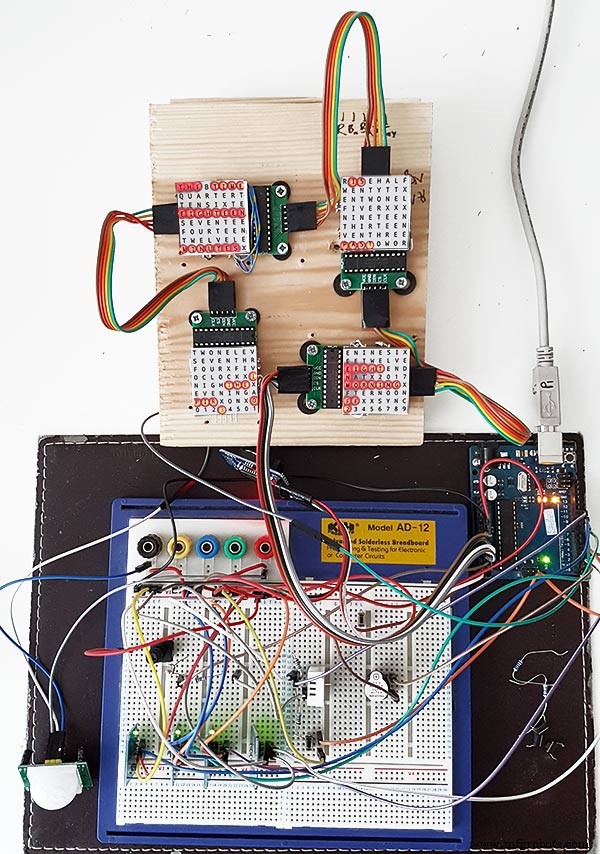
Маленькая кнопка под датчиком температуры / влажности используется для проверки 30-секундной синхронизации. Модули сенсорных кнопок находятся в левом нижнем углу макетной платы, сбоку. На этом прототипе не так много проводов, так как большая часть проводки находится в матрицах дисплея. На последних часах эта проводка будет проводиться вручную к отдельным светодиодам.
Я опробовал множество различных дизайнов слов и часов на этой доске, прежде чем попытаться построить окончательные часы.
Шаг 9:Тестирование измененных модулей
Я изменил эскиз Word Clock, чтобы можно было протестировать модуль MAX2719 после модификации проводки.
Вся эта программа по очереди зажигает каждый светодиод от верхнего левого угла до нижнего правого угла матрицы.
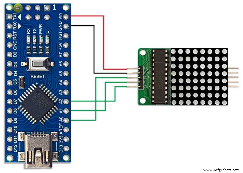
Просто подключите 5 проводов к модулю NANO и MAX2719 и запитайте NANO через порт USB. Загрузите эскиз и дайте ему поработать.
Просто подключите каждый модуль по очереди, чтобы проверить проводку.
Загрузите тестовый эскиз из прилагаемого zip-файла.
MAX7219_LED_Test.zip
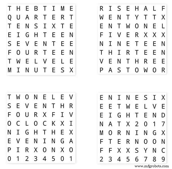
Шаг 10:Время до сопоставления слов
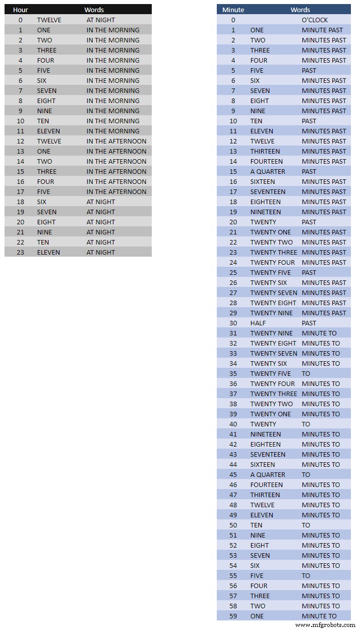
В таблице выше показано время до сопоставления слов.
Для этого нет никаких жестких правил, просто задайте слова так, как вы бы сказали время.
В своих часах я изменил следующее по сравнению со словами на часах Воутера.
«МИНУТЫ» изменились на «МИНУТЫ» через 1 минуту и 1 минуту на час. Добавлен "A" перед прошедшим "QUARTER" и "QUARTER" к часу.
В полдень изменил время на ДВЕНАДЦАТЬ ЧАСОВ В ДНЕ.
В полночь изменили время на ДВЕНАДЦАТЬ ЧАСОВ НОЧЬЮ.
После полуночи часы всегда показывают УТРО.
Эти изменения очень легко реализовать в программном обеспечении часов.
Слово% 2Bto% 2BTime% 2BTranslations.xlsx
Шаг 11. Питание
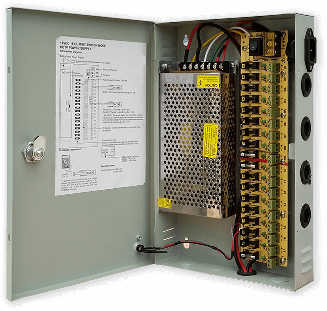
Я использую общий блок питания на 12 В для управления множеством различных типов цепей по всему дому. Затем этот источник питания 12 В локально понижается в каждой цепи с помощью модуля на 5 В для питания платы управления и различных модулей.
Мой общий блок питания состоит из 18 цепей на 12 В с индивидуальными предохранителями, каждая с предохранителем на 2 А. 9 из них имеют резервное питание от батарей. Платы часов также имеют собственный встроенный предохранитель.
Если вы используете только эту одну цепь, то подойдет любой регулируемый источник питания на 5 В до тех пор, пока он может обеспечивать ток для использования в вашей цепи.
Я разработал плату питания на Vero, в которой используется миниатюрный блок питания MP1584. Это преобразует выходное напряжение 12 В от моего обычного источника питания в 5 В для часов.
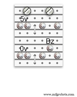
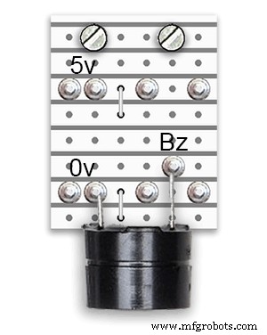
Есть две дополнительные платы питания, построенные из платы Vero.
Помимо того, что в одном держится зуммер, они просто добавляют дополнительные точки распределения питания для силовой проводки часов.
Требования к питанию
Я измерил ток, потребляемый часами, и при низкой яркости они потребляют 30 мА и 250 мА при полной яркости. Это, конечно, будет зависеть от количества горящих светодиодов. В яркий солнечный день уровни яркости, указанные на серийном выходе, равны 10. Это примерно 2/3 максимальной мощности светодиодов. Общее энергопотребление можно значительно снизить, если включить ИК-датчик. Дисплей погаснет, если часы не обнаружат движения.
Я бы использовал источник питания минимум 500 мА для питания часов. Мощность будет во многом зависеть от типа используемых вами светодиодов.
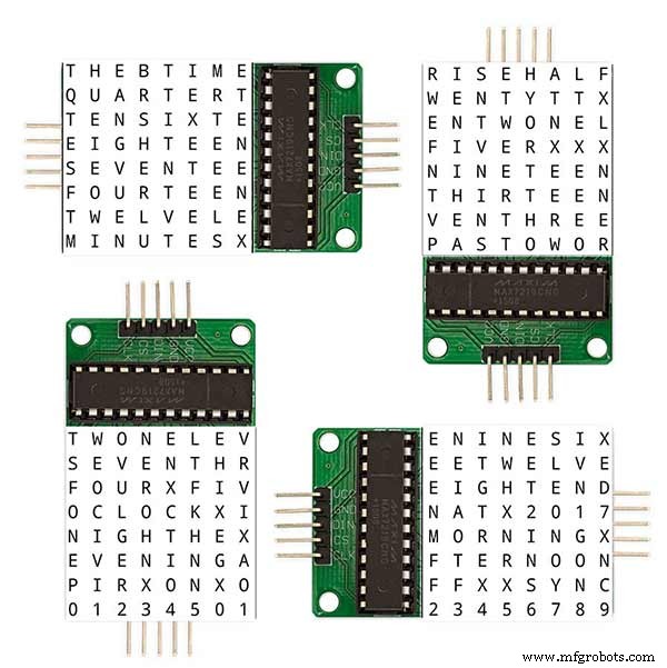
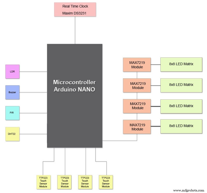
Шаг 12. Соединения модулей
На рисунке выше показано, как подключаются модули. Большинство модулей подключаются напрямую к Arduino Nano.
Платы MAX7219 подключаются к NANO только через модуль 01. Остальные модули подключаются последовательно друг к другу.
Затем каждая матрица светодиодов 8x8 подключается к модулю MAX7219.
Основная часть проводки - это соединения между модулями MAX7219 и светодиодными матрицами.
Сохраняйте расстояние между NANO и 1-м модулем MAX7219 и между модулем MAX7219 и модулями как можно короче. Также убедитесь, что вы подаете питание на оба конца подключенных гирляндой MAX7219, поскольку большая часть энергии потребляется этой частью цепи.
Шаг 13:Построение Порядок сборки
Порядок сборки предполагает, что сначала будут выполнены все прототипы и изменения программного обеспечения.
Распечатайте переводную виниловую пластинку.
Разрезать стекло.
Вырежьте листы МДФ спереди и сзади.
Вырежьте в лицевом листе отверстия для светодиодов.
Покраска листов МДФ.
Вырежьте в стекле отверстия для датчиков.
Наклейте виниловый перевод на заднюю часть стекла.
Вырежьте отверстия для датчиков в передней панели МДФ.
Вырежьте фальцы модуля датчика на передней панели.
Вырежьте заднюю панель из МДФ и сделайте 4 отверстия для доступа к датчику.
Добавьте меламиновые кромочные полосы на плиты МДФ, белые на переднюю панель и черные на заднюю.
Прикрутите заднюю панель МДФ к передней панели МДФ.
Сделайте платы Vero, 1 плату питания и 2 платы распределения питания.
Измените 4 платы MAX7219 и добавьте проводку к светодиодам.
Подключайтесь только на конце MAX7219.
Установите все модули и платы Vero на заднюю часть передней панели из МДФ.
Соберите все 4 светодиодные матрицы на передней панели из МДФ и припаяйте 256 светодиодов.
Подключите все провода Batt и Earth к плате питания Vero и платам распределения питания.
Подключите все электрические линии ко всем модулям.
Подключите всю проводку к модулям Nano, MAX7219, часам реального времени, датчику температуры, сенсорам касания и зуммеру.
Подключите все жгуты проводов от модифицированных плат MAX7219 к светодиодным матрицам в соответствии с таблицей электрических соединений.
Подключите модуль PIR удаленно от часов и подключите подключение PIR.
Подключите 30-секундную синхронизацию к вашим Master Clock (если требуется).
Закрепите стеклянную переднюю панель дисплея с помощью болтов Chicago, одновременно фиксируя сенсорные датчики.
Тест.
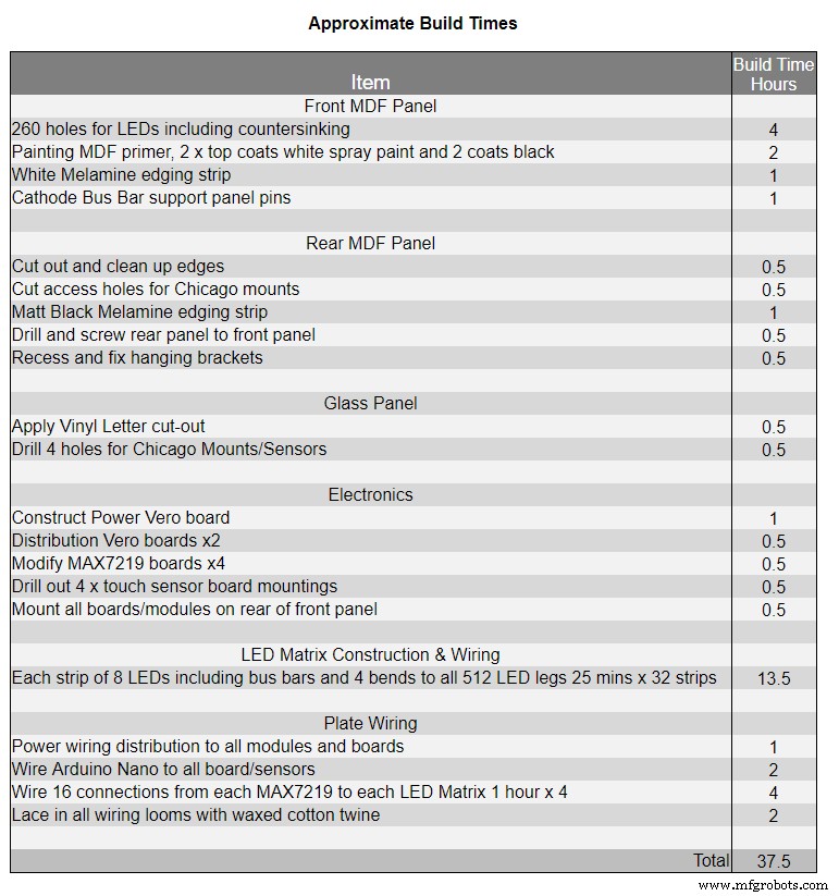
В таблице 1 показано очень приблизительное время сборки этих часов, которое будет варьироваться в зависимости от вашего уровня навыков, а также от имеющихся у вас специальных инструментов / рабочего места.
Вы можете легко добавить к этому списку еще 40 часов на прототипирование и программирование.
Шаг 14:строительная виниловая наклейка
Виниловая наклейка
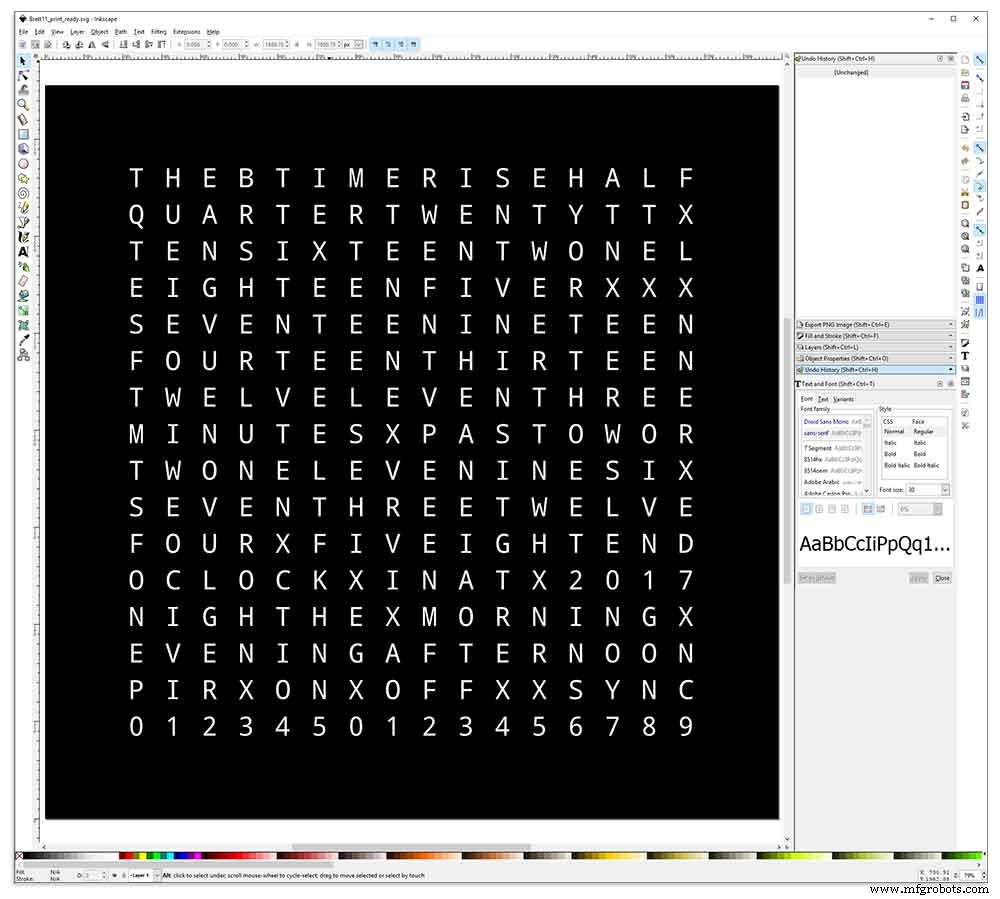
Виниловая наклейка разработана в Inkscape.
Inkscape - это программное обеспечение для векторной графики профессионального качества, работающее в Windows, Mac OS X и GNU / Linux. Он используется профессионалами в области дизайна и любителями во всем мире для создания разнообразной графики, такой как иллюстрации, значки, логотипы, диаграммы, карты и веб-графика.
Inkscape использует открытый стандарт W3C SVG (масштабируемая векторная графика) в качестве собственного формата и является бесплатным программным обеспечением с открытым исходным кодом.
Я загрузил оригинальный дизайн Inkscape от Воутера Девинка из его репозитория на GitHub, а затем изменил его в Inkscape в соответствии со своим дизайном. Я опробовал множество различных версий на своем миниатюрном прототипе, прежде чем отправить окончательный вариант на печать.
Не забудьте напечатать наклейку с обратной стороны!
Я использовал компанию Regal Signs &Graphics, которая поставила мою наклейку из черного винила, с вырезами в обратном направлении, с удаленными буквами и с лентой для аппликации, всего за 27 фунтов стерлингов с НДС.
Хотя они для меня довольно местные, я заплатил немного больше и получил свою наклейку в красивой защищенной картонной тубе.
У меня было несколько проблем с получением дизайна в правильном формате для их машины, но в конце концов я отправил его из Illustrator в формате eps, очень полезные люди из Regal Signs уменьшили его до нужного для меня размера. Мой файл Inkscape можно скачать здесь ВИНИЛОВЫЙ СТИКЕР.
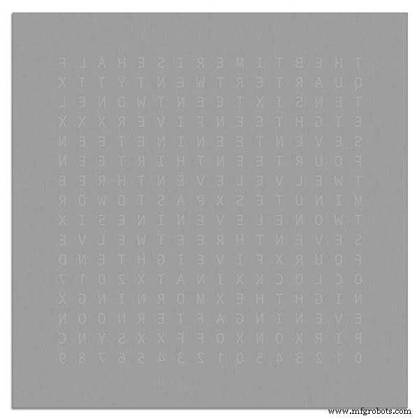
Виниловая наклейка была получена от Regal Signs, буквы были удалены, что сэкономило мне много времени. Наклейка поставляется с пластиковой лентой на лицевой (стеклянной) стороне и аппликационной бумагой сзади. Обычно вы отклеиваете боковую ленту, наносите наклейку, а затем удаляете бумагу для нанесения. Я решил оставить прикладную бумагу, поскольку она служила рассеивателем для светодиодов. Оставляя бумагу для аппликации включенной, я обрезал лишнюю бумагу вокруг наклейки перед нанесением.
Наклеить стикер было относительно просто. Просто убедитесь, что вы посмотрите несколько видеороликов YouTube о применении виниловых стикеров на стекле, прежде чем попробовать сами.
Стекло

В часах используется 4-миллиметровое флоат-стекло, размер которых составляет 500 x 500 мм. По мере того, как края обнажены, края также были отполированы - все это было сделано моими местными стекольщиками за 20 фунтов стерлингов.
Затем в стеклянной панели просверливали 5-миллиметровые отверстия с помощью 5-миллиметрового сверла для стекла. Посмотрите видеоролики на YouTube о том, как сверлить отверстия в стекле.
Сначала я очистил стекло ацетоном и убедился, что на нем нет пыли (очень важно). Затем я надел пластиковые перчатки, чтобы убедиться, что на наклейке не осталось отпечатков пальцев.
Я опрыскал стекло очень разбавленной смесью мыла и воды, а затем очень медленно снял пластиковую пленку с наклейки, обнажив лицевую поверхность.
Важно снимать пленку медленно и под очень острым углом, чтобы буквы на наклейке оставались связанными с копировальной бумагой. Когда наклейка полностью обнажится, нанесите ее на влажную поверхность стекла.
Смесь воды и мыла позволит вам переместить наклейку в нужное место на стекле. Затем используйте кредитную карту и отойдите от центра наклейки, чтобы удалить пузырьки воздуха. Оставьте наклейку сохнуть на ночь, затем срежьте виниловую пленку над 4 монтажными отверстиями в стекле.
Brett11_print_ready.svg
Шаг 15:Строительство основных плат, часть 1
Основные платы
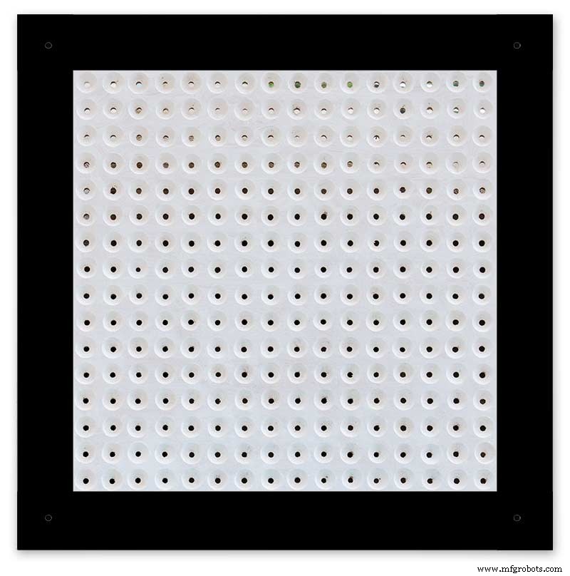
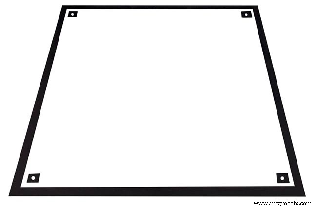
Основная плата часов состоит из 2 листов МДФ толщиной 14 мм. Задний лист на 10 мм меньше верхнего со всех сторон, кроме верха. Верх имеет белые края, а задний - черные. Если смотреть на стену, то кажется, что часы имеют глубину 14 мм.
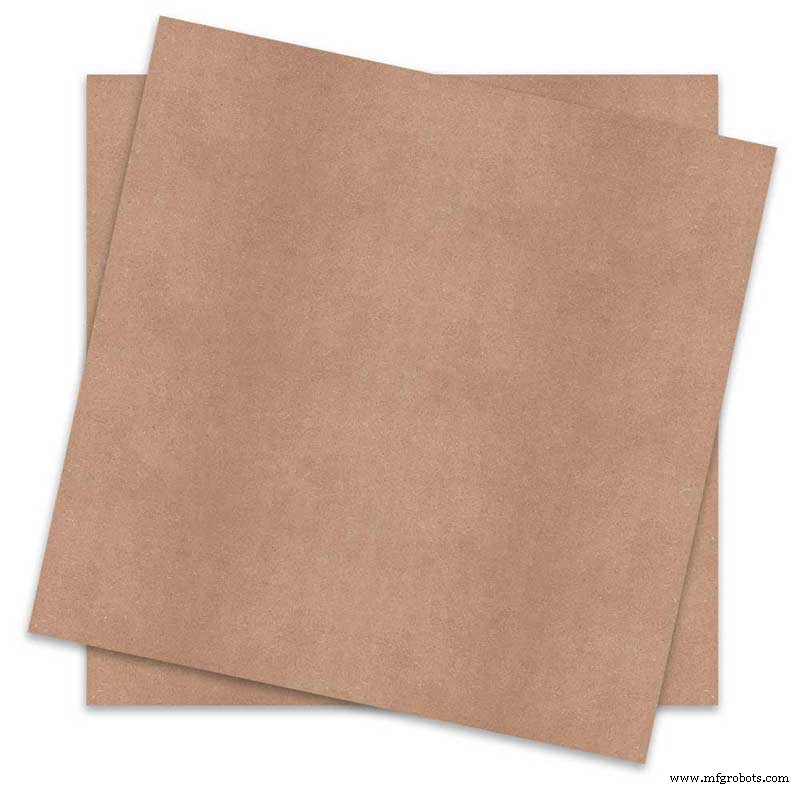
Основная плата часов состоит из 2 листов МДФ толщиной 14 мм. Задний лист на 10 мм меньше верхнего со всех сторон, кроме верха. Верх имеет белые края, а задний - черные. Если смотреть на стену, часы будут иметь глубину 14 мм.
В оригинальных часах Wouter Devinck Clock и версии «Catalan» Pijuana используется один лист МДФ толщиной 18 мм с выемкой на тыльной стороне, чтобы освободить место для печатной платы и компонентов. Использование 2 листов МДФ означает, что заднюю панель можно просто вырезать лобзиком, а не тратить время на пыльную фрезеровку. Размер верхнего листа составляет 503 мм x 503 мм, чтобы обеспечить нахлест вокруг стекла на 1,5 мм. Это немного защитит стекло от ударов.
Щит вырезается лобзиком и оставляет 14 мм пространства для компонентов.
Самая глубокая печатная плата, включая компоненты, - это модули MAX 7219 глубиной 10 мм. По завершении задняя панель приклеивается или прикручивается к передней панели.
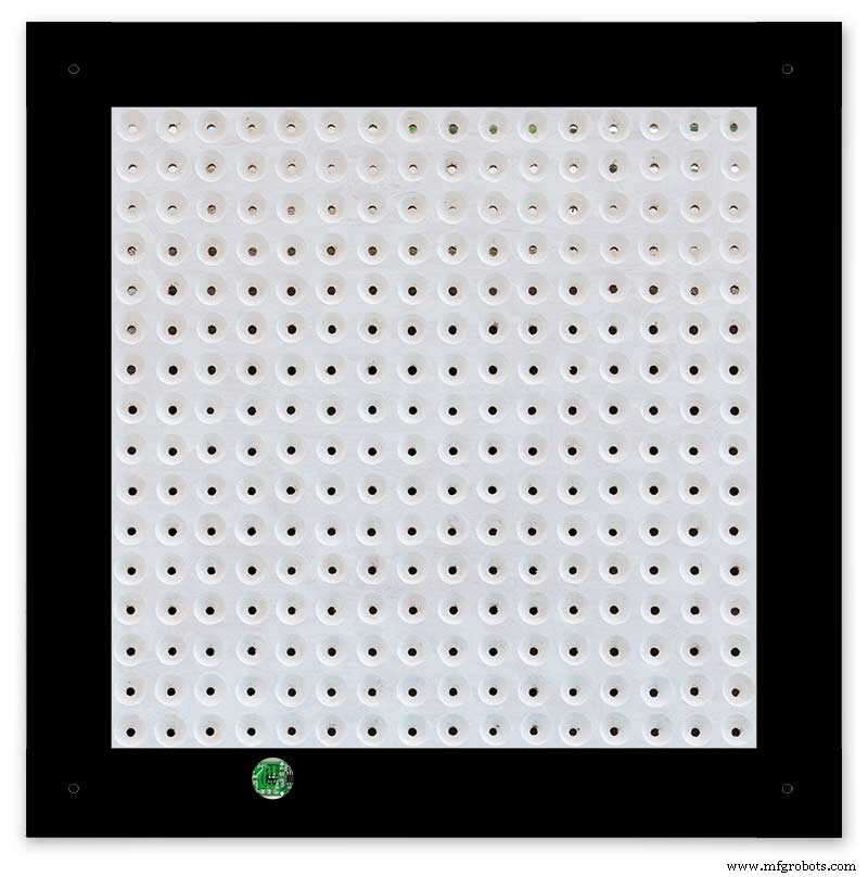
Конструкция передней панели
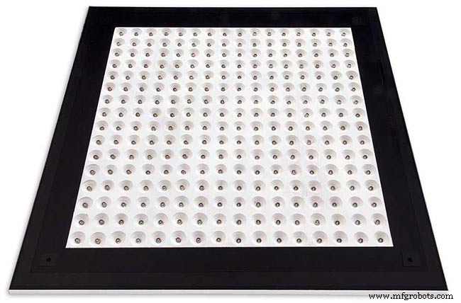
На передней панели размещены 256 светодиодов, которые светят через 6,5-миллиметровые отверстия и более широкие 18-миллиметровые отверстия с потайной головкой для подсветки отдельных букв и цифр на дисплее.
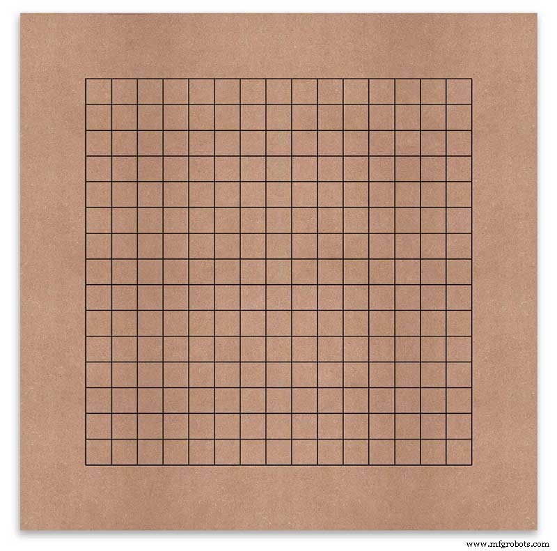
Доска помечена, чтобы показать положение сверления в центре каждого отображаемого символа. Используя 500-миллиметровый дисплей, я измерил свой виниловый лист, и символы находятся на расстоянии 25 мм друг от друга, начиная с 62,5 мм от краев. Я нарисовал эти линии на МДФ, пересечения были точками сверления.
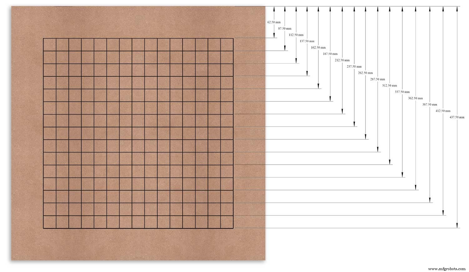
Я использовал верхний край в качестве опорной точки, которую я измерил, и отметил каждую строку с этой точки.
Это было повторено для вертикального столбца, используя левый край в качестве точки отсчета.
Пересечения сетки будут центральной точкой для 6-миллиметровых монтажных отверстий для светодиодов и 18-миллиметровых отверстий с потайной головкой.
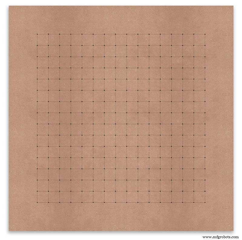
Using an automatic centre punch ( use a nail or screw if you don't have one) I punched the 256 intersection points of the grid.
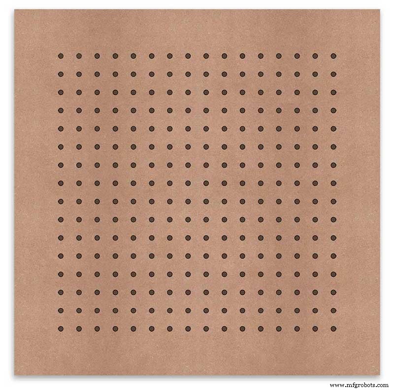
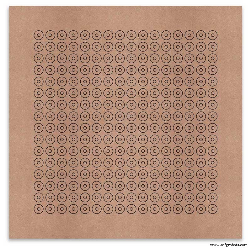
Using a drill bit to suite your LEDs (6mm in my case) and using the punched holes as a guide for the drill bit drill out all 256 LED mounting holes.
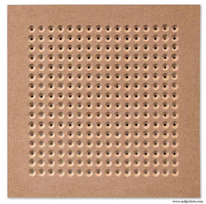
The next task is to drill the 256 18mm countersunk holes using a 20mm countersinking bit.
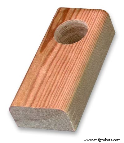
To keep the countersunk holes at a uniform depth and width I built a countersinking jig using an off cut of wood. To make the jig a hole is drilled in the wood off cut to just fit the silver rotating bezel of my drill chuck. Using a test piece of MDF the countersinking bit is then moved in and out of the chuck until a countersunk hole of the correct diameter is made when drilling through the hole upto the chuck in the off cut of wood. Once the correct distance is found the chuck is tightened and the main board is drilled 256 times by centring the hole in the wood over the existing 6mm holes then drilling down until the chuck bezel hits the hole in the countersinking jig.
Completed front board with 256 countersunk holes and 6mm holes for the LEDs.
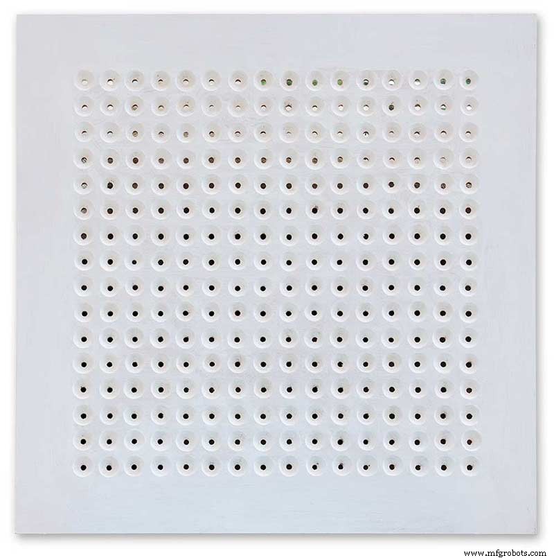
The board is then rubbed down and primed using MDF primer and painted white so the countersunk holes reflect the light from the LEDs.
A black edge is painted around the outside edge to hide the board as the glass is 1mm shorter all round. This setback also helps the glass disappear from view on the final clock.
Four 5mm holes are then drilled in the corners to take the Chicago Fasteners. The Chicago Fasteners hold the glass in place, hold the touch sensors and provide a touch sensitive pad on top of the glass. The fasteners have 3mm shafts and will have a small bit of rubber tape wrapped around the shafts to protect the glass.
Turn the board over and drill a rebate with a forstner bit to take the four touch sensors. This hole will be offset from the hole drilled in the previous step.
Wall Mounts
The clock is fixed to the wall by two metal picture hanging mounts.
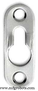
These are recessed into the frame so the highest point of the bracket is level with the frame.
Two 2" countersunk No6 screws sit in these bracket and hold the clock to the wall with a bit of tension so the dust seal is compressed.
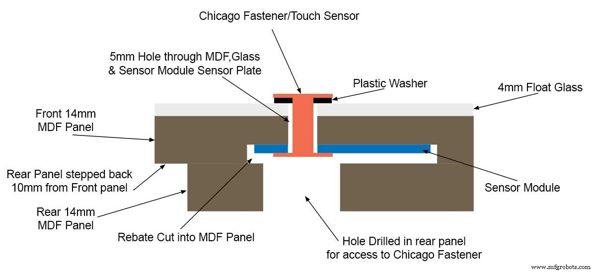
Step 16:Construction Touch Sensor Mounting
The touch sensor modules are fixed to the front panel using the Chicago Fastener bolts. The Chicago Fastener bolts then act as touch sensors.
A 5mm hole is drilled through the sensor pad on the module to allow the Chicago Fastener bolt to pass through.
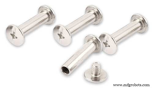
The sensor pad is insulated by the MDF panel and a plastic washer.
The touch pad on the sensor module has a 5mm mounting hole drill through the sensor.

Touch sensors in rebates behind rear panel. Holes drilled into rear panel allows access to the Chicago Fasteners that hold the sensors/glass front in place.
Clock front panel with four Chicago Fastener tops acting as touch plates.
Step 17:Electronic Components &Modules
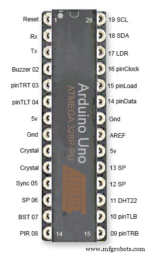
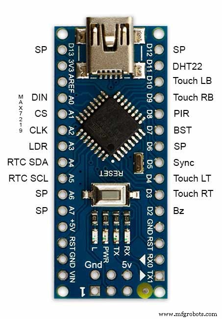
ATmega328 pin connections in case you want to prototype the circuit on an Arduino Uno. Note BST pin 07 is not used.
Pin label numbers refer to Arduino IDE numbers.
LEDs
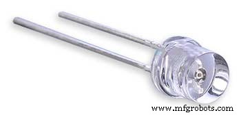
Make sure you purchase your LEDs from a good source. These LEDs will be on for many hours a day. I have has problems with LEDs failing after a few weeks use.
My LEDs Specs
5mm White Flat Top LEDs offering a pure and consistent colour with a wide angle ultra bright light output.
Colour :White
Quantity :256
Lenses Type :Round Flat Top
Crystal ClearBrightness :13000mcdForward
Voltage :3.2v - 3.8v
Forward Current :20mA (typical), 30mA (Max)
Viewing Angle :120 degrees
DHT22 Temperature &Humidity Sensor
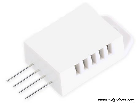
The DHT22 is a basic, low-cost digital temperature and humidity sensor. It uses a capacitive humidity sensor and a thermistor to measure the surrounding air, and sends out a digital signal on the data pin.
You can only get new data from it once every 2 seconds, so sensor readings can be up to 2 seconds old.
Simply connect the first pin on the left to 3-5V power, the second pin to your data input pin and the right most pin to ground.
To prevent the temperature of the inside clock case being measured the top and left side vent of the DH22 are covered over with tape. This also stops dust being drawn into the clock case.
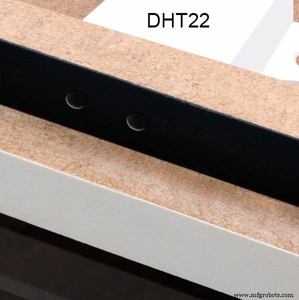
The DHT22 is mounted with its right open side mounted tight against the lower rear cover.Two small holes are drilled in the lower edge of the rear MDF board to allow air from the room to circulate around the sensor.
Arduino NANO
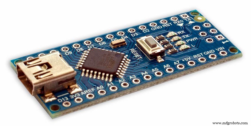
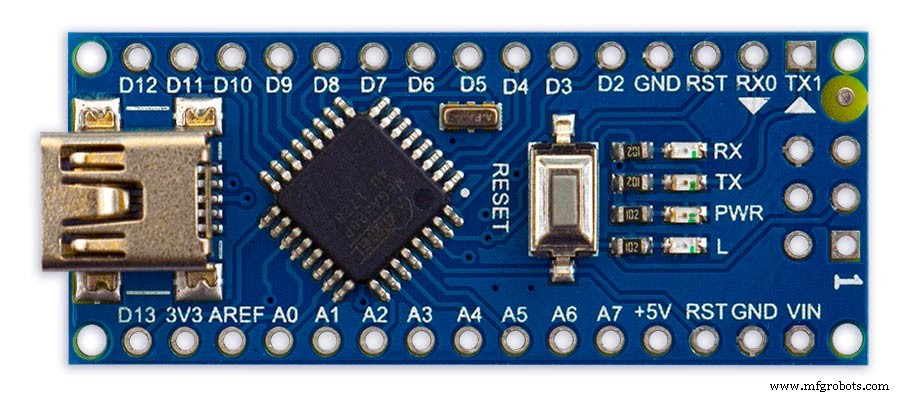
PowerThe Arduino Nano can be powered via the Mini-B USB connection, 6-20V unregulated external power supply (pin 30), or 5V regulated external power supply (pin 27). The power source is automatically selected to the highest voltage source.
Memory
The ATmega328 has 32 KB, (also with 2 KB used for the bootloader.
The ATmega328 has 2 KB of SRAM and 1 KB of EEPROM.
Input and Output
Each of the 14 digital pins on the Nano can be used as an input or output, using pinMode(), digitalWrite(), and digitalRead() functions. They operate at 5 volts. Each pin can provide or receive a maximum of 40 mA and has an internal pull-up resistor (disconnected by default) of 20-50 kOhms. In addition, some pins have specialized functions:Serial:0 (RX) and 1 (TX). Used to receive (RX) and transmit (TX) TTL serial data. These pins are connected to the corresponding pins of the FTDI USB-to-TTL Serial chip.
External Interrupts:2 and 3.
These pins can be configured to trigger an interrupt on a low value, a rising or falling edge, or a change in value. See the attachInterrupt() function for details.
PWM:3, 5, 6, 9, 10, and 11. Provide 8-bit PWM output with the analogWrite() function.
SPI:10 (SS), 11 (MOSI), 12 (MISO), 13 (SCK). These pins support SPI communication, which, although provided by the underlying hardware, is not currently included in the Arduino language.
LED:13. There is a built-in LED connected to digital pin 13. When the pin is HIGH value, the LED is on, when the pin is LOW, it's off.
The Nano has 8 analog inputs, each of which provide 10 bits of resolution (i.e. 1024 different values). By default they measure from ground to 5 volts, though is it possible to change the upper end of their range using the analogReference() function. Analog pins 6 and 7 cannot be used as digital pins. Additionally, some pins have specialized functionality:I2C:4 (SDA) and 5 (SCL). Support I2C (TWI) communication using the Wire library (documentation on the Wiring website).
There are a couple of other pins on the board:AREF. Reference voltage for the analog inputs. Used with analogReference(). Reset. Bring this line LOW to reset the microcontroller. Typically used to add a reset button to shields which block the one on the board.
Communication The Arduino Nano has a number of facilities for communicating with a computer, another Arduino, or other microcontrollers. The ATmega328 provide UART TTL (5V) serial communication, which is available on digital pins 0 (RX) and 1 (TX). An FTDI FT232RL on the board channels this serial communication over USB and the FTDI drivers (included with the Arduino software) provide a virtual com port to software on the computer. The Arduino software includes a serial monitor which allows simple textual data to be sent to and from the Arduino board. The RX and TX LEDs on the board will flash when data is being transmitted via the FTDI chip and USB connection to the computer (but not for serial communication on pins 0 and 1). A SoftwareSerial library allows for serial communication on any of the Nano's digital pins. The ATmega328 also support I2C (TWI) and SPI communication. The Arduino software includes a Wire library to simplify use of the I2C bus. To use the SPI communication, please see ATmega328 datasheet.
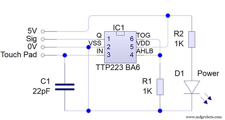
TTP223 Touch Sensor Module
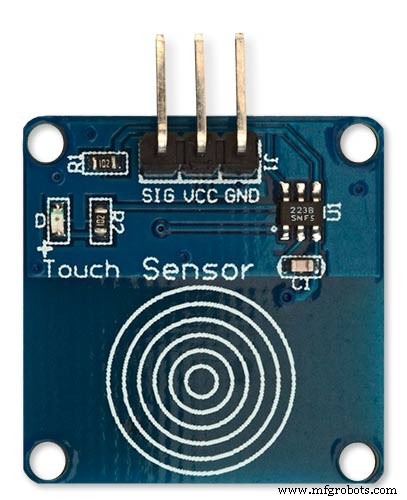
The touch Sensor Module is bolted to the front panel using the glass mounting bolts. The bolt goes through a 5mm hole drilled in the middle of the sensor.Note the mounting bolt is touched to trigger the sensor but is insulated from the sensor itself through plastic washers. Four of these modules are used in the clock one mounted on each corner of the glass.
Note the LEDs are not required and are removed from the modules (just break them off) to save power.
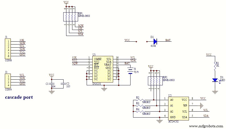
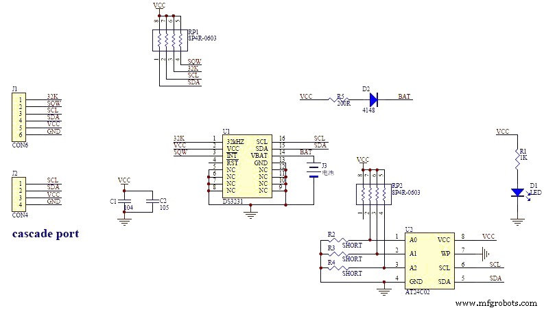
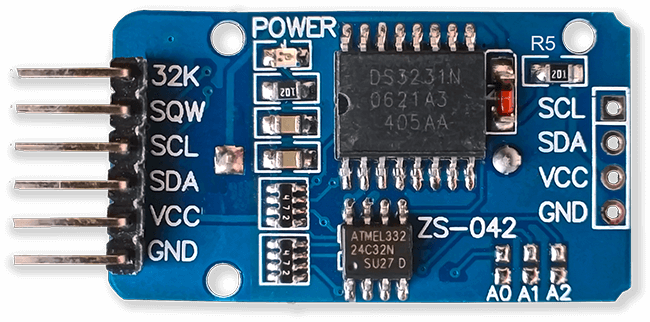
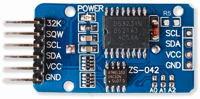
DS3231 AT24C32 I2C Precision Real Time Clock Module
My clock uses a DS3231 AT24C32 I2C Precision Real Time Clock Module.The module comes supplied with a Lithium-Ion rechargeable battery see diagram below. I use a non rechargeable battery so have removed resistor R5 from the module.
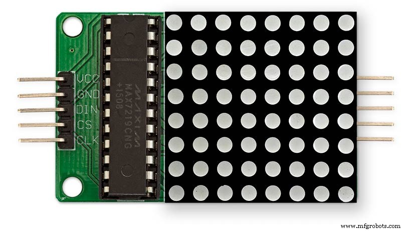
MAX7219 Display Module
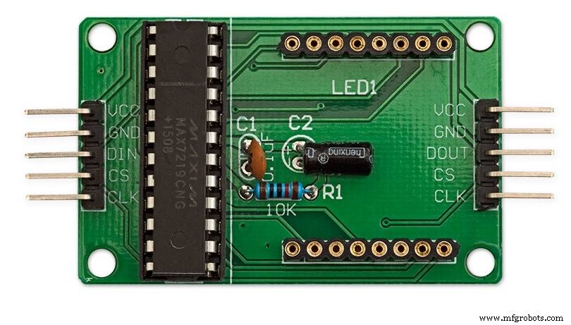
MAX7219 LED current limiting
The max current through the LEDs is set by a single resistor R1 on the module. The value of resistor can be found from the table below.
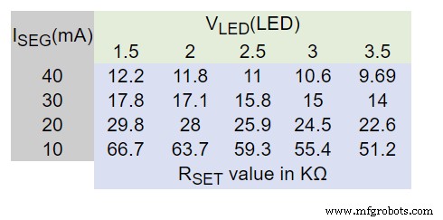
The module comes with a 10K resistor preinstalled but this can be removed and a resister to match your LEDs current added in its place. My LEDs Forward Voltage is 3.2v - 3.8v @ 20mA. They can handle 30mA max but for long LED life 20mA is best. I have used 22KΩ resistors which will limit the current to around 20mA when the light levels are at their peek.
See setting automatic brightness levels.
1088AS LED Dot Matrix display

1088AS LED Dot Matrix display view of lower edge Pins 1 to 8 left to right.
This is used for prototyping and is not required in the final project.
LDR
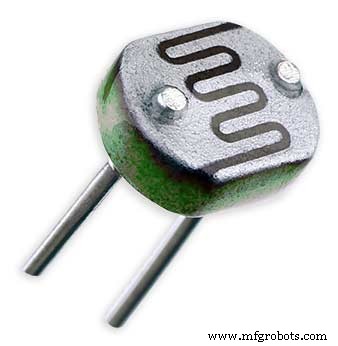
An LDR is used to sense the ambient light levels. The LDR is around 500Ω in bright light and 10MΩ in the dark.
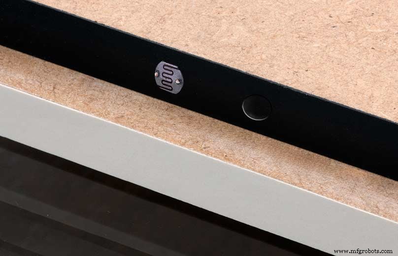
The LDR is positioned underneath the clock on the rear MDF panel.
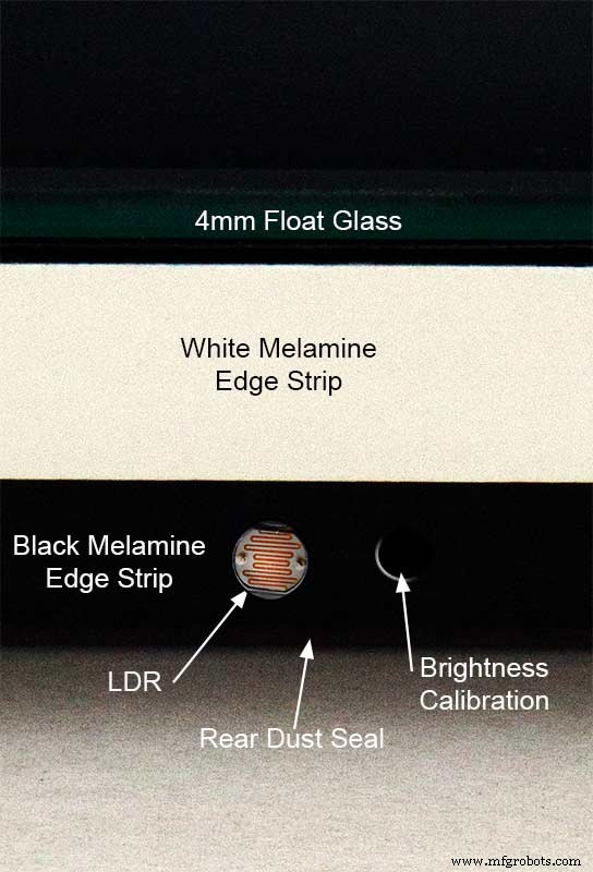
Next to the LDR is a hole to give access to the trimmer resister to calibrate the LED brightness control.
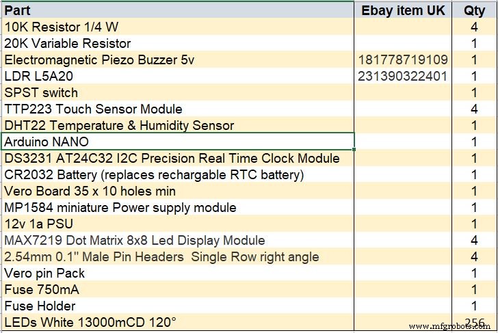
Component List
Step 18 Dust Seals
To prevent ingress of dust two dust seals are fitted.
On the rear MDF board a 2mm soft foam rubber dust seal is fitted. When the clock is hung on its hanging hooks the seal is under pressureand seals the back of the clock to the wall.
The seal is self adhesive and is fitted with a 5mm gap to the edge of the rear MDF board.
On top of the front board to prevent dust getting under the glass a strip of self amalgamating rubber is fitted 5mm from the board edge.
To prevent the glass from cracking when the Chicago bolts are tightened 4 small square of rubber are also fitted around the holes in the glass.
I punched holes for the Chicago Bolts in the rubber with a leather punch.
Step 19:Schematic
Nano Connections
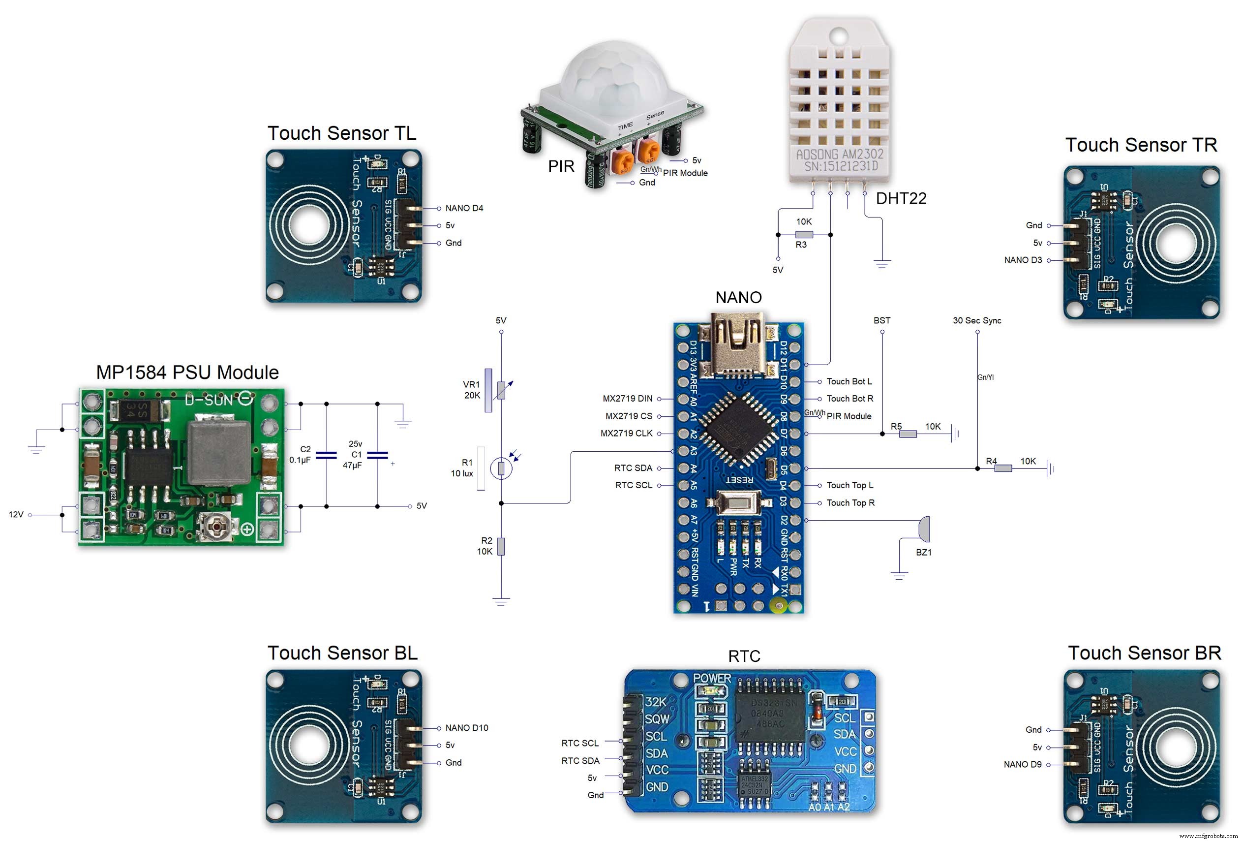
The connections to the Arduino Nano. Download the full size file from the hardware section
MAX2719 connections


The 4 MAX7219 modules and the connected LED matrixes.
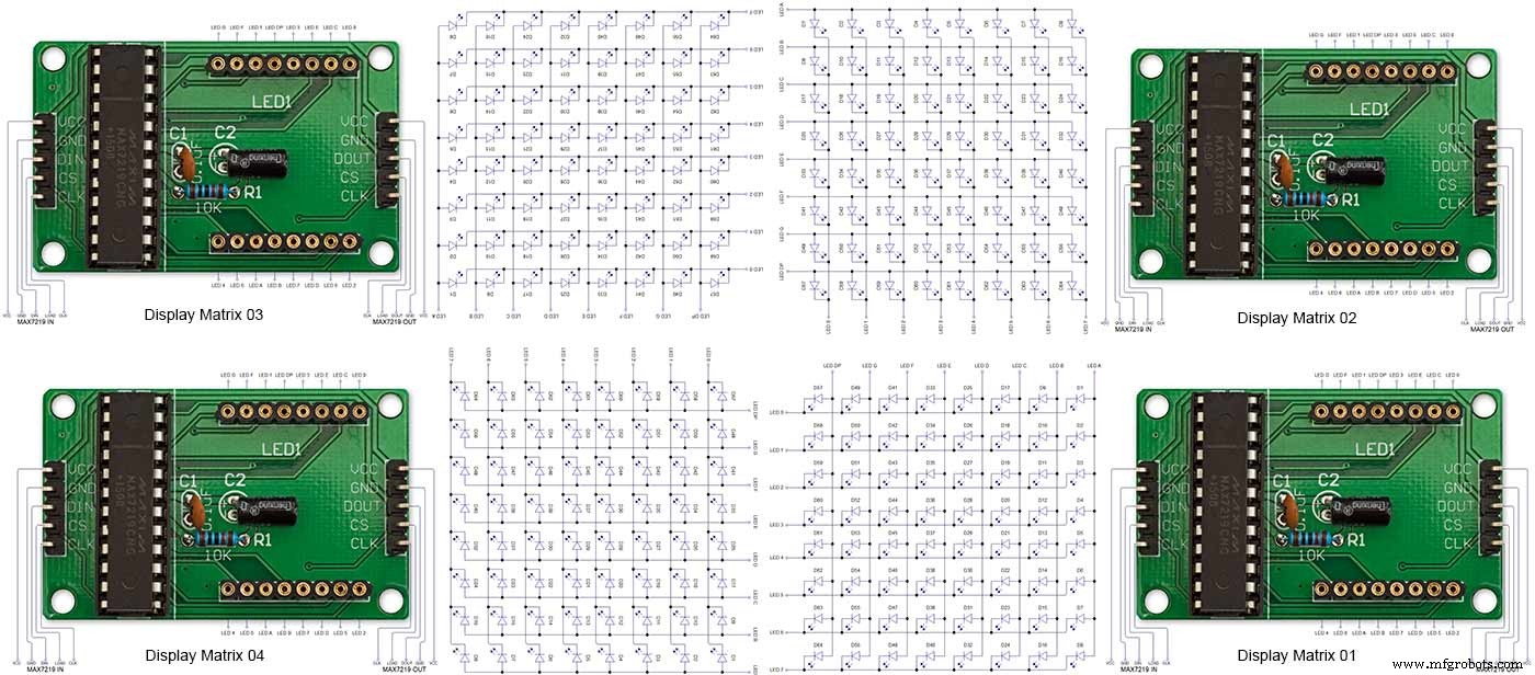
Note the LED display matrixes are rotated anti-clockwise 90 degrees from each other starting from display matrix 01.Display Matrix 01 input is wired to the Arduino CLK, DIN and LOAD the output is taken to the input of Display matrix 02 etc etc.
Step 20:Wiring Building the LED Matrixes
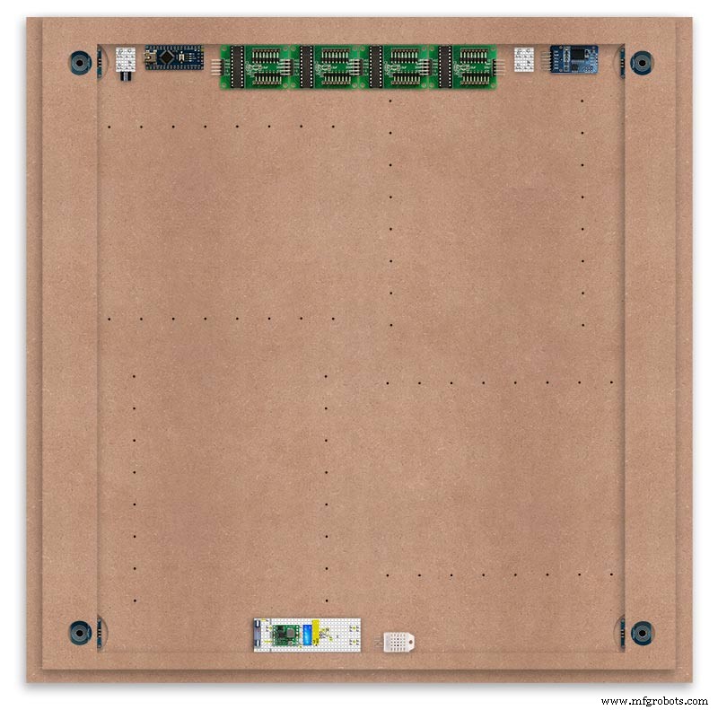
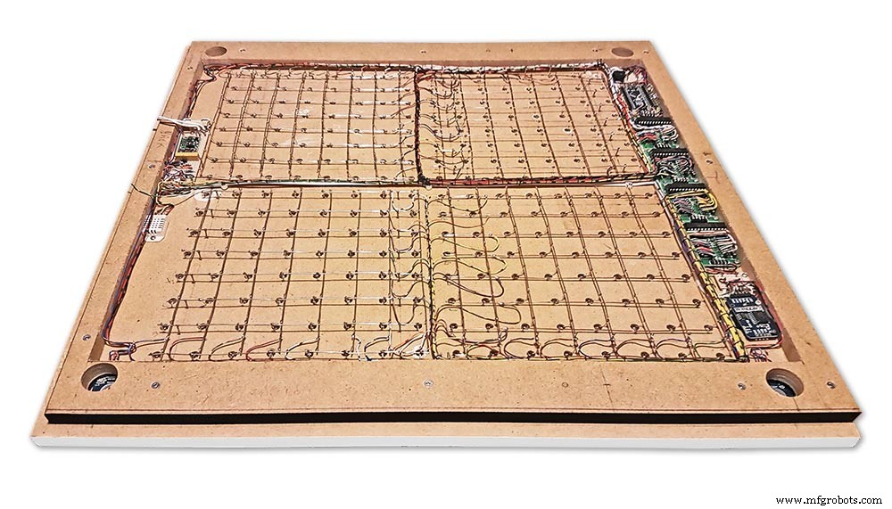
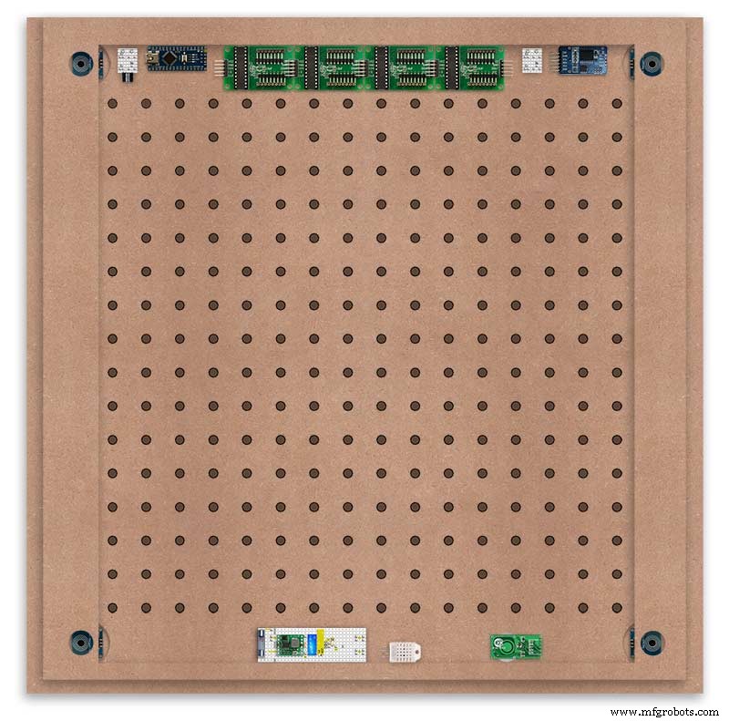
Module Locations

The module locations are shown above. The four sensors are located in the recesses on the main board behind the rear board. Holes are cut into the rear board to allow access for fit the Chicago Bolts/Sensor pads.
The four MAX7219 Display Modules are soldered together and are mounted in the centre top of the board. This keeps the data links between the boards as short as possible.
The Arduino Nano is mounted on the left of the MAX7219 Display Modules and the RTC on the right. The RTC battery holder on the base of the RTC module is recessed into the main board.
The Vero board containing the power module is located on the lower part of the board. There are two power distribution boards mounted on the top of the clock. The main 5v 2A feed cable is taken to both of these boards and power is then distributed to the other boards from these points.
The MAX7219 board power is fed from the left board and daisy chained through each board then taken out the forth board to ensure they are fed with 0v and 5v from both ends.
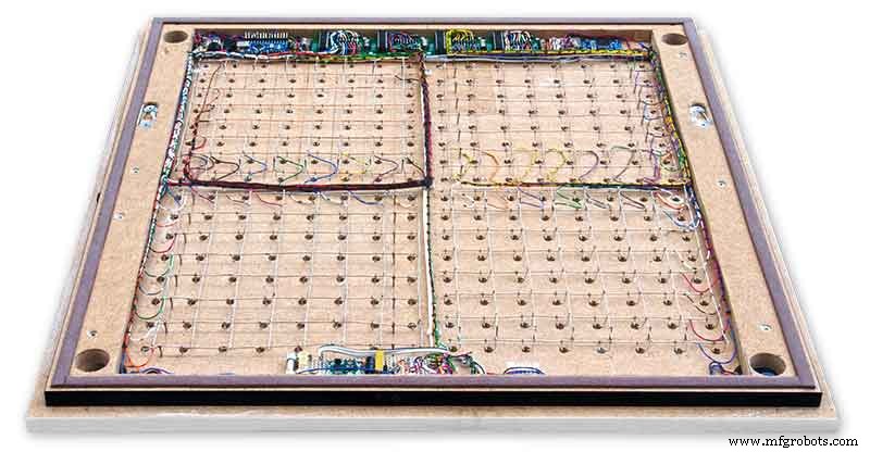
The LED locations are shown. The LED matrixes each contain 64 LEDs and are labelled 1 to 4.
These correspond to the 4 MAX 7219 modules mounted above numbered 1 to 4 left to right. Note this is the rear of the clock so number will be revearsed.
The LED Matrixes are built up off 2 types of BUS Bars per module. A Cathode Bus at 10mm high and an Anode BUS bar at 2mm high.
There are 8 Cathode and 8 Anode BUS Bars per module. Each module has 16 x 15mm panel pins hammered into the board in the position shown to support the 10mm high Cathode BUS.
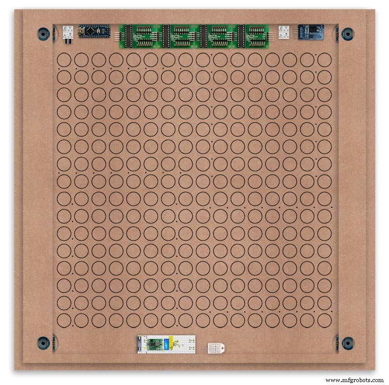
The 15mm panel pins are hammered in 5mm (I used a 10mm piece of metal bar as a gauge) leaving 10mm as Cathode BUS bar support pins.
As shown above the pins correspond with the thick parts of the board not the recess for the LEDs on the front of the board. Note the LED recess is on the front of the board and can't be seen from the back.

0.9mm copper wire is then soldered to each pair of pins to form the Cathode BUS Bar.
Note the rotation of each module and also the modules are in reverse as it is the back of the board the LEDs are connected to.
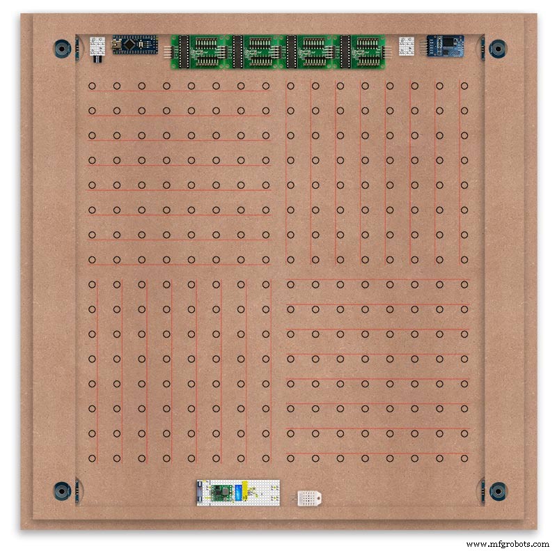
The Anode BUS Bars are shown below in Red and are supported off each LED Anode about 2mm off the MDF board. No Pins required.

Both Cathode &Anode BUS Bar locations are shown below.
Each LED is connected to an Anode and Cathode of the Matrix.
Step 21:Wiring the LEDs
LEDs
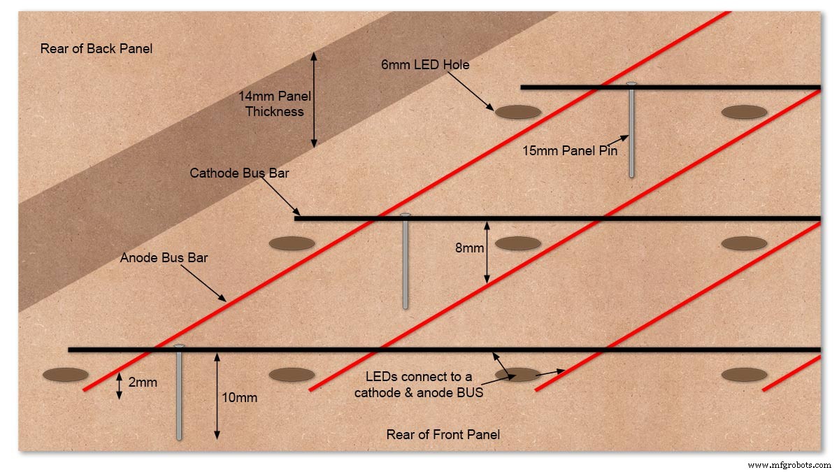
Diagram showing Bus Bar layout with panel pins supporting the Cathode Bus. This module has horizontal Cathode and vertical Anode Bus Bars.
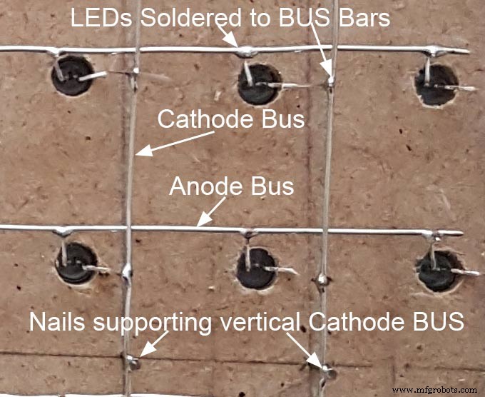
Close up section of Module wiring.The Cathode BUS Bars run vertically and the Anode BUS Bars run horizontally on this module. The Anode &Cathode BUS Bars have an 8mm vertical separation.
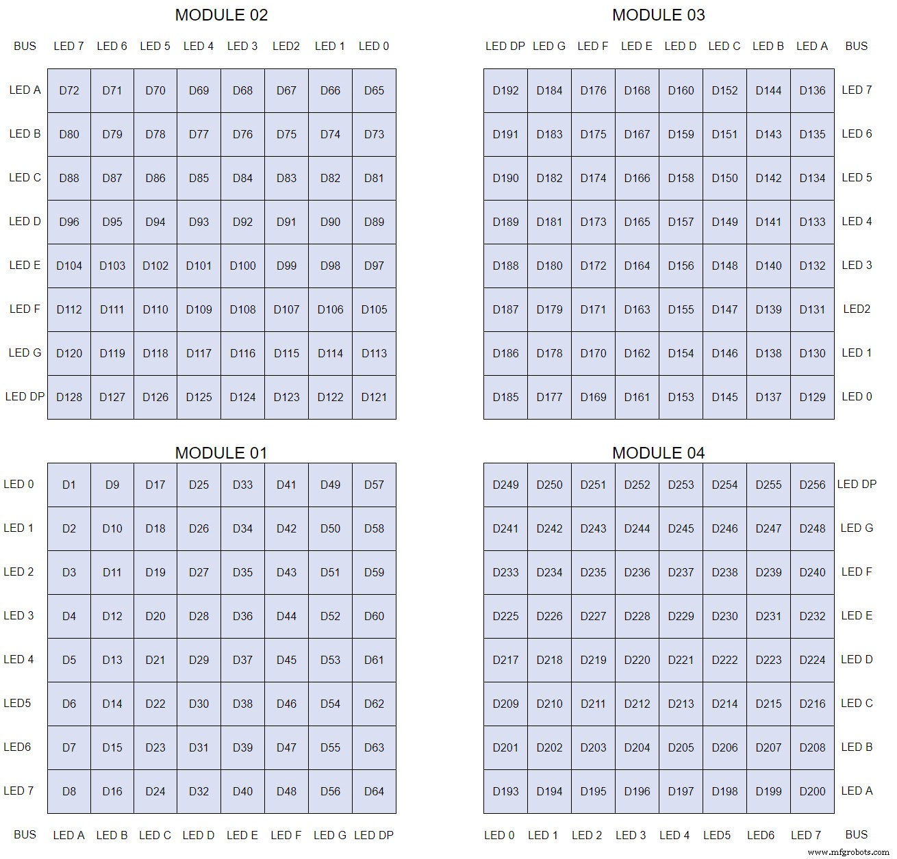
The LEDs are connected to the matrixes and MAX7219 modules from the rear. The LED positions will be reversed and of course rotated 90° relative to the next module. This makes it very complicated connecting the correct LEDs and Bus bars from the rear of the board. The table below shows the LED positions in the blue boxes with the BUS Bar matrix position in black around the outside as they appear from the back of the front MDF board.
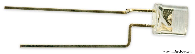
The LEDs are bent in a jig to keep the position in the display constant and to speed up construction. Each LED has four bends two on each leg that's 1024 in total! The Cathode leg is bent 90° from the Anode.
The Matrix grids are wired to the corresponding pins on the MAX7219 modules according to the layout table.
There are 16 wires to each module.
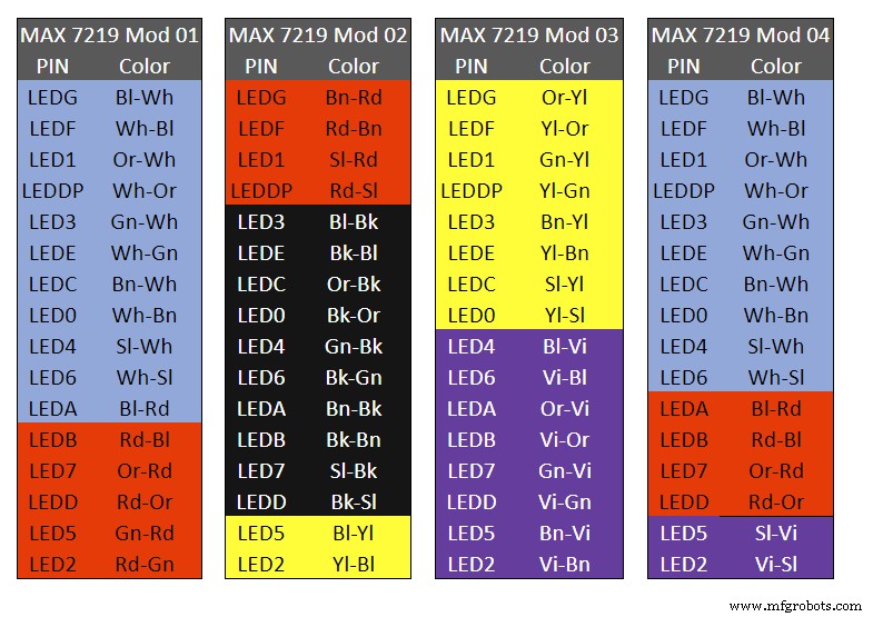
Table 1 Module LED Matrix Wiring Colour Code is shown above.
Each Module has 16 wires connecting it to the LED Matrixes. I have used 50pr 0.5mm cable so the last 14pr colours are duplicated. On Mod 4 I went out of order and missed out the Sl/Vi at the start so have put it in at the end.
Step 22:Wiring Modifying the MAX7219 Modules
Before wires can be connected to the MAX 2917 modules they will need to be modified.
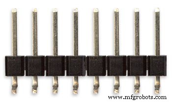
Two sets of 8 90° pin connectors will to be soldered to the lower edge of the existing LED matrix connector.

Modified MAX7219 module with 90° pin connectors soldered in place to the bottom of the old LED Matrix connectors.
Wires are taken away from these points to the LED matrix on the main MDF board as per the LED Matrix Wiring Colour Code table on the previous step.
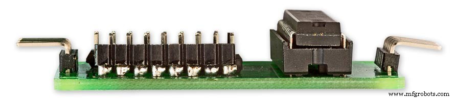
Side view showing the pins soldered to the side of the old LED Matrix connector pins just above the PCB.
Note if your MAX7219 Module does not have surface mount components the 90° pin connectors may need to be trimmed back so they don't foul R1, C1 or C2.
MAX7219 LED current limitingThe max current through the LEDs is set by a single resistor R1 on the module. The value of resistor can be found from the table below.

The module comes with a 10K resistor preinstalled but this can be removed and a resistor to match your LEDs current added in its place.
My LEDs Forward Voltage is 3.2v - 3.8v @ 20mA. They can handle 30mA max but for long LED life 20mA is best. I have used 22KΩ resistors which will limit the current to around 20mA when the light levels are at their peek.
Note this sets the max current through your LEDs actual brightness is controlled by the LDR/software/ trimmer resistor and will usually be far less than this.
Setting Automatic Brightness Levels
The clock automatically senses the ambient light and adjusts the LEDs accordingly.
When first installed the clock will need to be calibrated to the maximum light levels in its actual location.

Connect a mobile, laptop/tablet etc via a suitable cable to the mini USB port of the clock and open an app to monitor the serial port.
I use Slick USB 2 Serial Terminal on my S7 via an OTG cable and USB to mini USB cable.
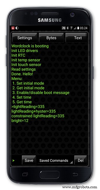
The clock will reboot and after the initial start screen you will see the following data updating down the screen.
You don't need to worry about lightReading or constrained lightReading+hyster just light reading, and bright.
With the clock in position and the ambient light at its maximum levels carefully insert a flat bladed jewellers screwdriver into the access hole just to the right of the light sensor.
Turn the screwdriver slowly until the light reading =600 (or your level set in brightness.cpp) and bright =15.
Your clock will now go to max brightness when the ambient light is at its maximum.
If you turn the screwdriver too far the light reading will go over 600 but the bright reading will not increase.
If you want the clock to be dimmer right across the range of ambient light levels adjust the light reading to a level less than 600 at max ambient light levels.
Note when bright=15 this will output the max current to the LEDs. The max current is set by R1( RSET) on the MAX7219 module and this should be chosen for your type of LED used in the display.
Step 23:Wring Mini USB Port
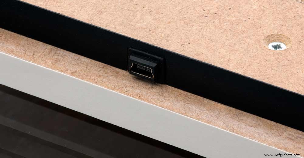
To allow adjustment/checking of light levels and programming of the clock a Mini USB socket is cut into the right hand side of the rear MDF sheet.
I have used a 25cm 90° Right angle Mini USB Male to Female Extension Cable and stripped back the insulation sleeve and shielding to expose the wires. This allows the cable to bend around the sharp angles and tight spaces of the enclosure.
Step 24:PIR Controlled Display Shutdown
This is optional as a Doppler Radar module can be fitted inside the clock instead.
See next section.
The PIR when enabled on the word clock menu (bott left PIR On, bott right PIR Off) turns on the display when movement is detected in the room.
When no movement is detected the display turns off after a set period of time. When the PIR is enabled the displays shows "PIR ON" and when disabled (display always on) it shows "PIR OFF" Note when the PIR is not enabled the display is always On.
The PIR module is fitted remote from the clock in a modified chrome light switch box. The box is cut into a plasterboard wall and also contains a switch to turn the clock off. The module itself is very small and can be mounted in a tiny enclosure if you don't want it on show. It will not work behind glass so if you wanted to mount it on the clock a hole would need to cut in the glass. This is very easy to do with a large hole cutter.
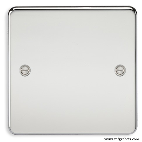
A blank chrome switch plate and back box are used to house the power switch and PIR module.
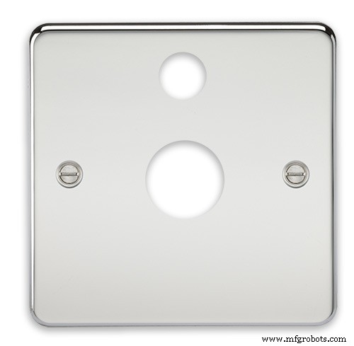
Two holes are drilled in the blank switch plate for the power switch and PIR lens.
The hole are centre punched, pilot drilled and then drilled out just big enough for a step cutter to fit through. The hole for the PIR diffuser is cut just big enough for the lens to go through with a friction fit.
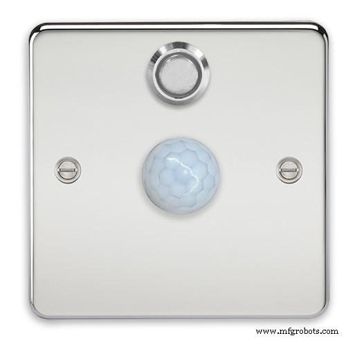
The completed switch plate.
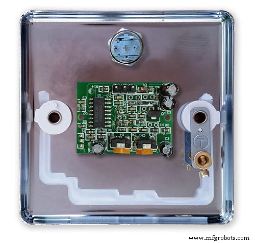
The 12 volt supply +ve is terminated on the switch with the 0v terminated on the earth screw.
12 volts is then fed back upto the clock PSU Vero board from the other side of the switch and again the earth screw. 5 volts are fed from the clock PSU Vero board to supply the PIR module.
The 5 volts and PIR sensor wire to the clock terminate on PCB header sockets. These are is plugged into the PIR Module header pins. The sync cable is terminated on a header pins and connects to the Master Clock 30 second sync cable via a single header socket.
The PIR has 2 trimmer resistors for adjusting sensitivity and also length of time the PIR &display stay activated.
PIR On/Off Control:The PIR is turned on and off in word clock mode by touching the bottom left sensor to turn the PIR on or by touching the right sensor to turn the PIR off. Note when the PIR is set to off the display stays on permanently. When you change the PIR setting the work "PIR ON" or "PIR OFF" is displayed for 5 seconds.
When initial power up the default is PIR off if you switch the PIR On straight away the display will go off as the PIR takes a minute or so to initialise before detecting movement.
Photo 6 &7 "PIR ON" or "PIR OFF" are displayed for 5 seconds when PIR setting is changed.
Step 25:Doppler Radar Control Option
Optional Doppler Radar Module can be added in place of the PIR above.
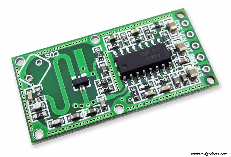
The Doppler Radar when enabled on the Word Clock menu (bott left PIR On, bott right PIR Off) turns on the display when movement is detected in the room. A check is made for motion on every quarter hour. When no movement is detected the display turns off until movement is detected again.
When the PIR is enabled the displays shows "PIR ON" and when disabled (display always on) it shows "PIR OFF" Note when the PIR is not enabled the display is always On. Unlike PIR modules the Doppler Radar module can see through glass and plastic and is fixed into the case of the clock behind the glass and PVC sticker. The module has a range of around 5m or 16' 5".
Doppler Radar Module fixed inside the case. A hole is drilled in the front panel to allow the module to monitor the room.
Front panel showing hole through to the Doppler Radar module microwave sensor.
The module is hidden from view behind the PVC sticker and glass.
Step 26:PIR/Doppler Radar On Off Control
The PIR is turned on &off in word clock mode by touching the bottom left sensor to turn the PIR on or by touching the right sensor to turn the PIR off.
Note when the PIR is set to off the display stays on permanently.

When you change the PIR setting the work "PIR ON" or "PIR OFF" is displayed for 5 seconds.
When initial power up the default is PIR off if you switch the PIR On straight away the display will go off as the PIR takes a minute or so to initialise before detecting movement.
Step 27:Setting Automatic Brightness Levels
The clock automatically senses the ambient light and adjusts the LEDs accordingly.
When first installed the clock will need to be calibrated to the maximum light levels in its actual location. Connect a mobile, laptop/tablet etc via a suitable cable to the mini USB port of the clock and open an app to monitor the serial port. I use Slick USB 2 Serial Terminal on my S7 via an OTG cable and USB to mini USB cable.

The clock will reboot and after the initial start screen you will see the following data updating down the screen.
You don't need to worry about lightReading or constrained lightReading+hyster just light reading, and bright.With the clock in position and the ambient light at its maximum levels carefully insert a flat bladed jewellers screwdriver into the access hole just to the right of the light sensor. Turn the screwdriver slowly until the light reading =600 (or your level set in brightness.cpp) and bright =15. Your clock will now go to max brightness when the ambient light is at its maximum. If you turn the screwdriver too far the light reading will go over 600 but the bright reading will not increase.
If you want the clock to be dimmer right across the range of ambient light levels adjust the light reading to a level less than 600 at max ambient light levels.
Note when bright=15 this will output the max current to the LEDs. The max current is set by R1( RSET) on the MAX7219 module and this should be chosen for your type of LED used in the display.
Step 28:Setting the Clock
The clock is set in the digital clock mode by touching the bottom left sensor.
The hour digits will now flash twice a second to indicate the clock is in time setting mode.In this mode the sensors have the following functions.
Top right - steps the hours or mins digits up
Top left- steps the hours or mins digits down
Bottom left 1sr press - enters the time setting mode selecting hours digits
Bottom left 2nd press -selects the mins digits for changing
Bottom left 3rd press -exits time setting mode and sets the time
Bottom right - resets the seconds to 00
Step 29:Synchronisation
If you have connected a 30 second master clock sync cable then the clock will jump back or forward to 30 seconds when out of time setting mode. If you don't have a Master Clock to sync to then the clock will fall back on the on board temperature compensated real time clock which in itself is a very precise quartz clock.
Just reset the seconds roughly in sync to the seconds (within 10 seconds either way) and wait for the clock to sync once out of time setting mode.
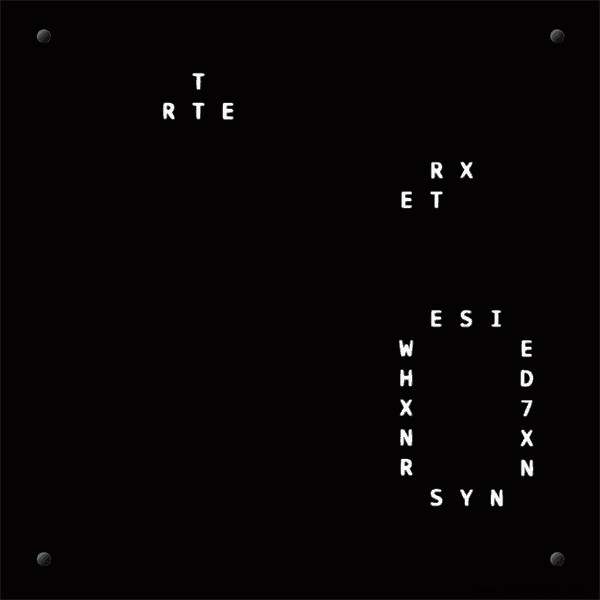
The animated loop below shows the Word Clock is running fast by several seconds. A synchronisation pulse is received from the Master Clock every 30 seconds on the minute and half minute synchronising the clock on 30 seconds.
The clock will ignore the 30 second synchronisation pulse from the Master Clock at 0 seconds. Note clock synchronisation only happens when the Word Clock is 20 seconds past and 20 seconds to a minute. In normal operation the sync pulse corrects the clock to within a fraction of a second so you will see the word "SYNC" appear with no visible correction to the seconds.
Note the synchronisation pulse is received every 30 seconds but the clock will ignore pulses at 0 seconds.
Step 30:Software &Making Changes
The software can be downloaded from the software tab and contains the following modules.
Program Files Modules
Brett_wordclock_v4_3.ino Main program, latest update includes shortened code saving 10% in size.
Thanks to srdevil for providing the updated code for this seconds display.
brightness.cpp/.h Brightness autoadjustment
character.cpp/.h Character (digit) definitions
credits.cpp/.h Ending Credits
display.cpp/.h Display &LED functions
life.cpp/.h Game of Life
serial.cpp/.h Serial port setup menu
simon.cpp/.h Simon Says game
temphum.cpp/.h Temperature &Humidity displa
tetris.cpp/.h Tetris game
time.cpp/.h Wordclock, digital clock
timeanalog.cpp/.h Analogue clock
touchbuttons.cpp/.h Touch buttons, mode switching
Third party libraries:
Chronodot.cpp/.h Chronodot library (for DS3231)
DHT.cpp/.h Temperature sensor library (for DHT22)
LedControl.cpp/.h LedControl library (for MAX7219)
stc.cpp/.h/platform.h Simple Tetris Clone library
pitches.h Note frequencies from the Arduino webpage
When you want to make changes to my code you can compare my code to the "Catalan Code" to make it easier to understand what changes you need to make. I have added //Brett to my code to highlight my changes.
Changing the code.
If like me you are not very good at coding just play around with the code to get an understanding of how it works.
I just save a different version each time I make even a tiny change. This way if I mess up I can go back a version and start again.
If you are keeping my linear seconds display update the version number on the display so you know what version you are trying out each time. This is done in the module credit.h around line 47.
It would take far too long to explain all the code but here is a very brief guide on how to change the words and when they are displayed.
The WORDS are set in time.h
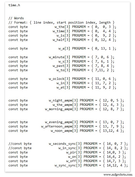
On line 52 we have
const byte w_the[3] PROGMEM ={ 0, 0, 3 };
The word "THE" is described in this line with the LED location in the curly brackets "{ 0, 0, 3 }"
This is the co-ordinate of the LEDs we are gong to light when we call "w_the"
The LED matrix numbers starts top left and start from 0 so "{ 0, 0, 3 }" is the first LED across and down the 3 just means the 3 LEDs across including this one will light. As the letters THE are in this position the word "THE" is displayed.
Similarly the word "TIME" would be lit by lighting the four LEDs here { 0, 4, 4 } or row 0, 5th LED along and light 4 LEDs (remember to count from 0).
Working you way down the page shows the position of all the words.
Controlling when words are lit
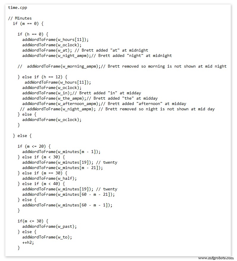
This happens in the module time.cpp
Here you just make a list of rules to tell the clock what words to light at certain times.
Pic above shows part of the code starting with line 695
At midnight we want to make the clock say "THE TIME IS TWELVE OCLOCK AT NIGHT"
Midnight is 00 00
"THE TIME IS" is always displayed from lines 687
So we add the rules if minutes are 0, then if hours are 0 show the word for hours "TWELVE" and the word "OCLOCK" the word "AT" and the word "NIGHT"
If you follow the code down all the possible time combinations are covered.
Analogue Clock Code Change - increase in time definition One of the comments sent to me by srdevil was some code changes. His comment can be seen below.
I have not had time to test the code but have included it below if you want to try it out.
" If the time is 18:00, it points up (long leg) and down (short leg). But when the time is 18:59, it still points totally down (short leg) so it looks like the time is 17:59 on a normal clock. My brother change the code so that if it is>HH:15 the small pointer moves already to the next number. As of this we also increased the resolution in the part between>HH:15 -
Code on the comments section or can be seen here http://home.btconnect.com/brettoliver1/Word_Clock/Word_Clock.htm#analogeclock
Код
- Brett_wordclock_v4_5.zip
Brett_wordclock_v4_5.zipArduino
Load into Aduino IDENo preview (download only).
Github
https://github.com/wouterdevinck/wordclockhttps://github.com/wouterdevinck/wordclockGithub
https://github.com/svcabre/wordclockhttps://github.com/svcabre/wordclockMy Word Clock on GITHUB
Schematics and code https://github.com/brettoliver/wordclockИзготовленные на заказ детали и корпуса
Vinyl Sticker Design in Inkscape (free to download) change as required brett11_print_ready_6bbpMTDyFa.svgСхема
Schemaic showing main board connections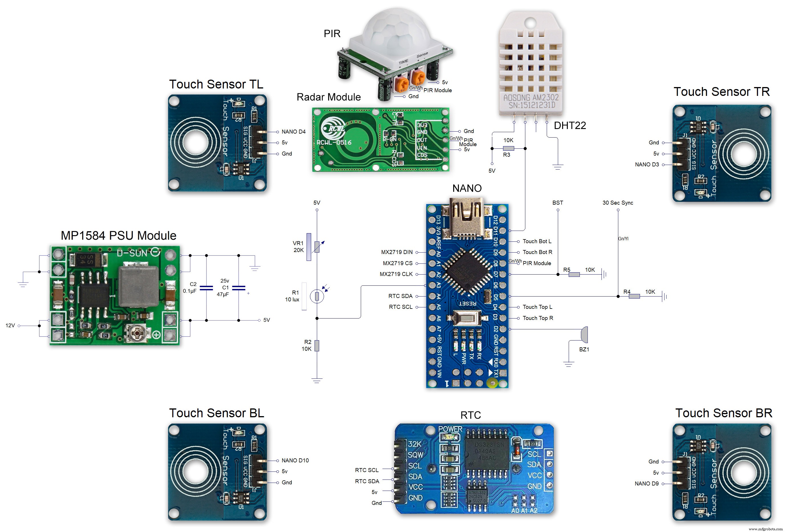 MAX7219 7 segment display module 01 LED connections
 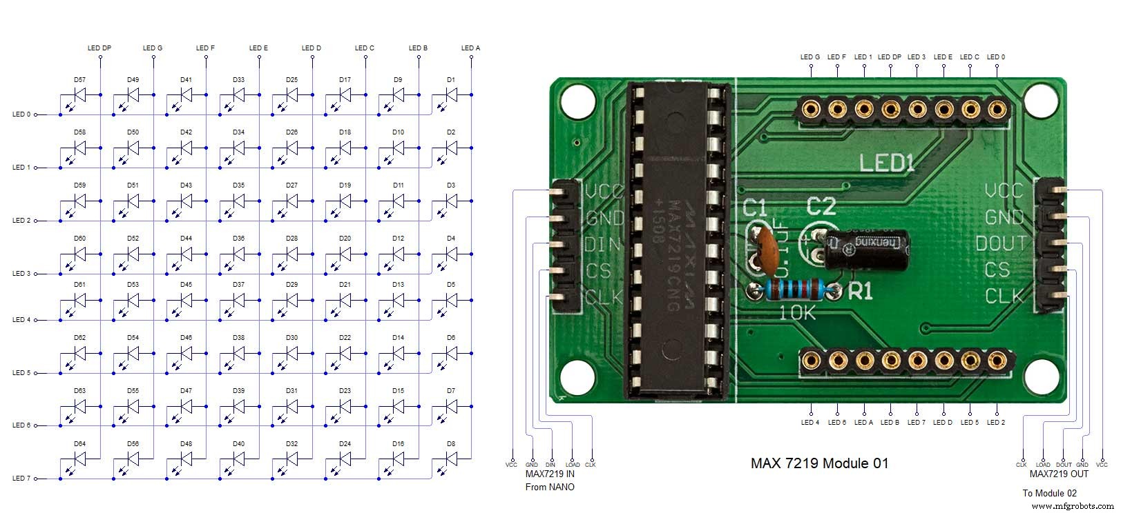 MAX7219 7 segment display module 02 LED connections
 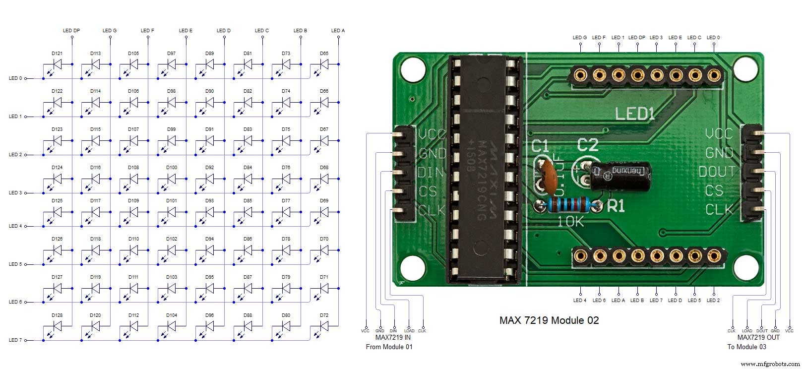 MAX7219 7 segment display module 03 LED connections
 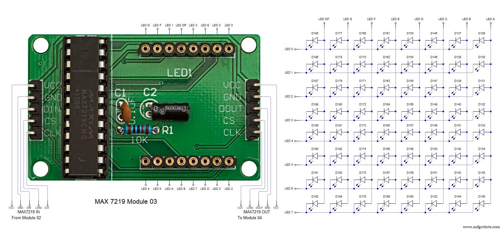 MAX7219 7 segment display module 04 LED connections
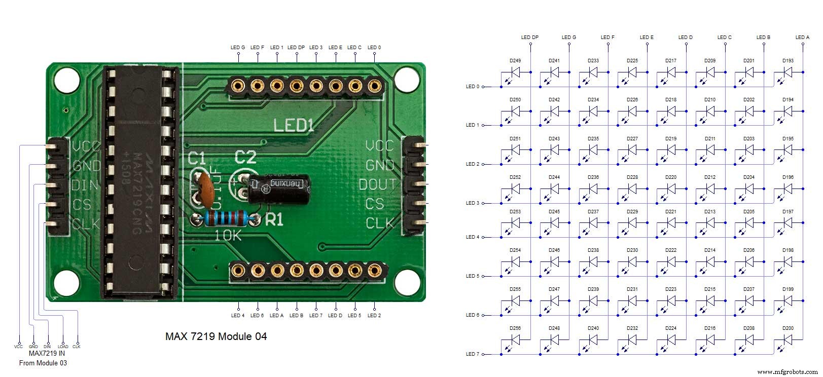
Производственный процесс
- Часы с кукушкой
- 3D-печать силиконом - время пришло?
- Считывание аналоговых датчиков с одним контактом GPIO
- Самодельные простейшие часы Numitron IV9 с Arduino
- Python Timeit() с примерами
- Простые часы со словами (Arduino)
- Часы Arduino с исламским временем молитв
- Уменьшите количество узких мест с помощью 5 простых инструментов
- Arduino Temp. Монитор и часы реального времени с дисплеем 3.2
- Простой будильник с DS1302 RTC