


Моторизованный слайдер камеры Arduino с управлением через Bluetooth
Компоненты и расходные материалы
 |
| × | 1 | |||
 |
| × | 1 | |||
| × | 1 | ||||
| × | 4 | ||||
| × | 4 | ||||
| × | 4 | ||||
| × | 4 | ||||
| × | 2 | ||||
| × | 2 | ||||
| × | 2 | ||||
| × | 2 | ||||
| × | 2 | ||||
| × | 4 | ||||
| × | 4 | ||||
| × | 8 | ||||
| × | 2 | ||||
| × | 1 | ||||
| × | 1 | ||||
| × | 1 | ||||
| × | 1 | ||||
| × | 1 | ||||
| × | 1 | ||||
| × | 1 | ||||
| × | 1 |
Необходимые инструменты и машины
 |
|
Приложения и онлайн-сервисы
 |
| |||
| ||||
 |
|
Об этом проекте
Обзор проекта
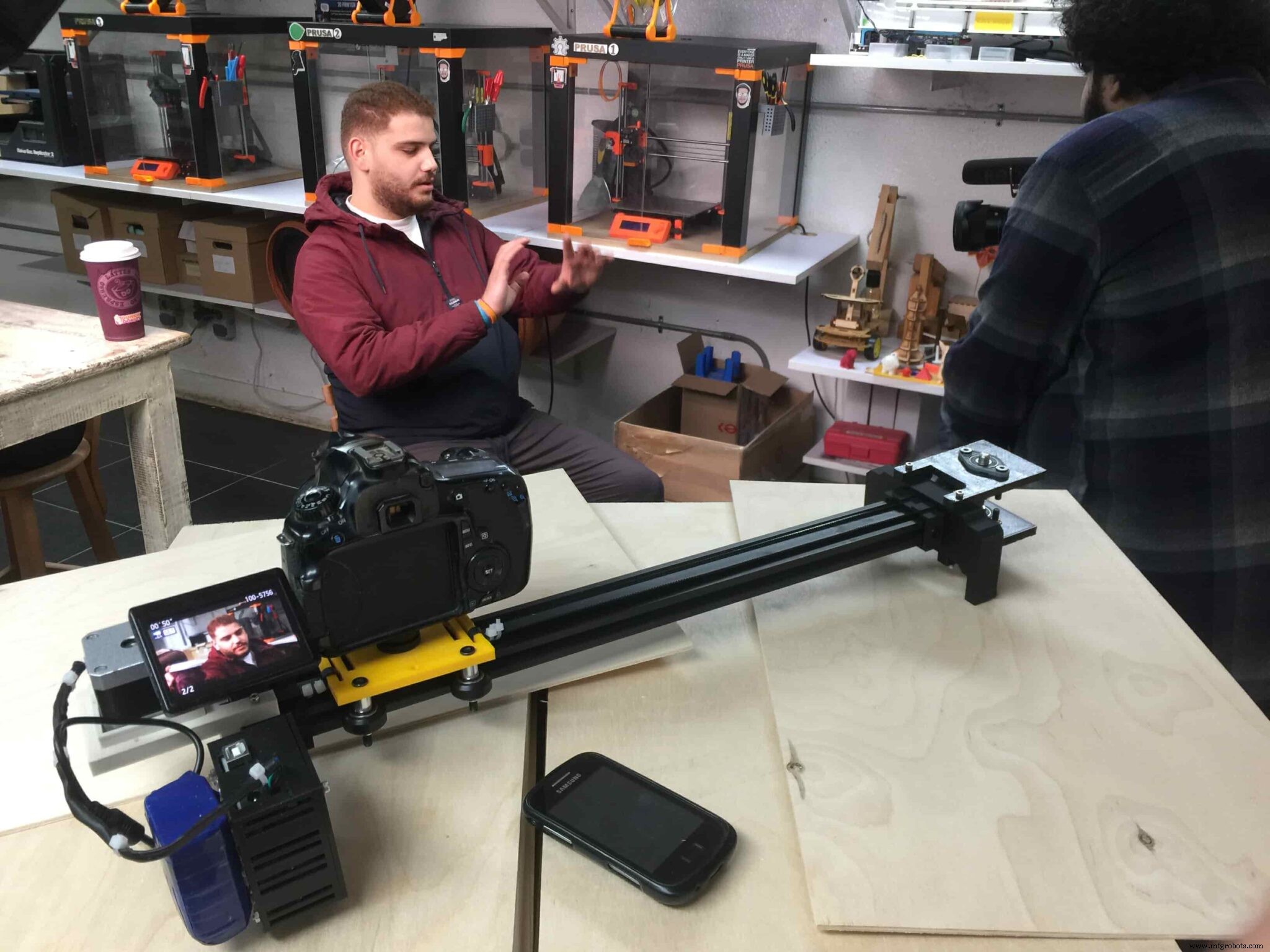
Для тех, кто любит снимать случайные любительские видео, покупать моторизованный слайдер для камеры как-то дорого. Итак, я построил свой собственный. В этом уроке мы рассмотрим каждый этап создания вашего собственного моторизованного слайдера камеры с управлением через Bluetooth.
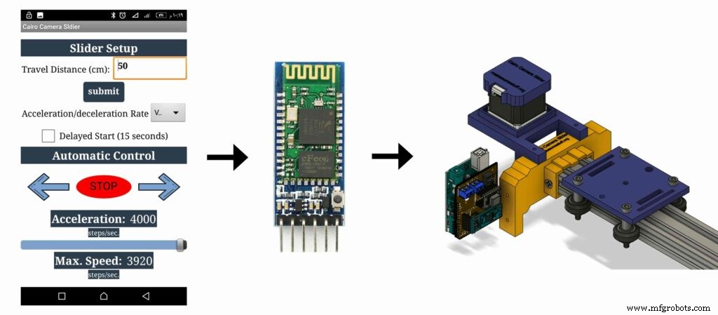
Сегодня мы создадим моторизованный слайдер камеры, которым мы сможем управлять им по беспроводной сети через Bluetooth из специального мобильного приложения для Android. Я использовал инструмент «Изобретатель приложений Массачусетского технологического института», чтобы создать приложение, которое дает нам возможность контролировать множество вещей, таких как скорость движения ползунка, расстояние перемещения, скорость ускорения / замедления и многое другое. Мобильное приложение очень надежное, внутри приложения вы можете установить длину слайдера камеры, который вы используете. Это означает, что вы можете создать свой настоящий слайдер камеры любой длины до 10 метров, не беспокоясь о приложении.
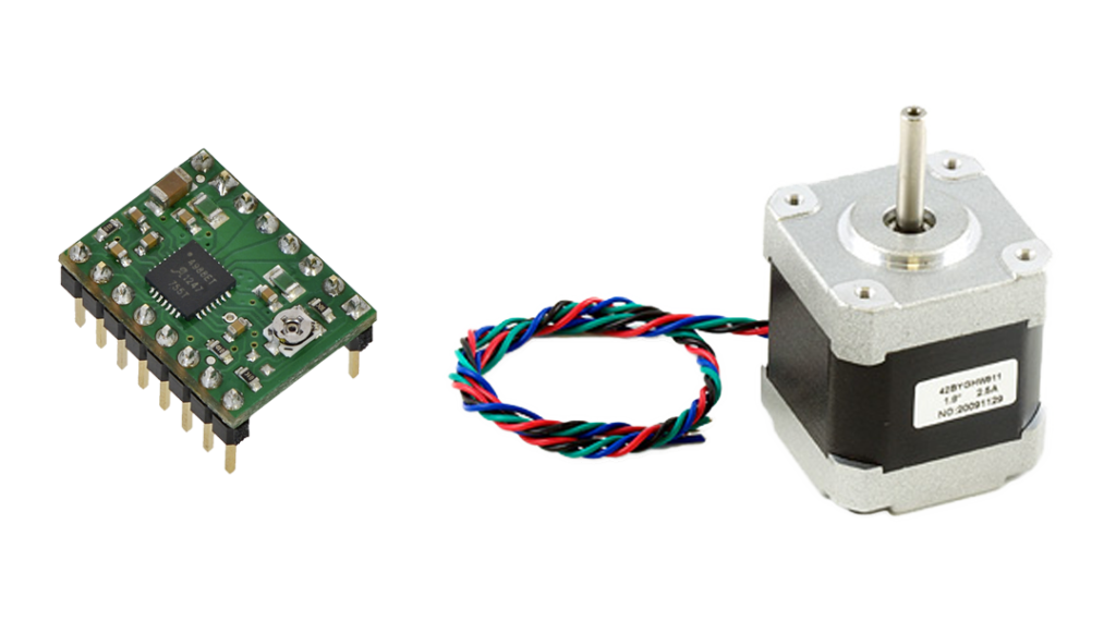
Мы использовали шаговый двигатель NEMA17 в качестве привода, поэтому мы можем контролировать, сколько шагов нам нужно, чтобы ползунок камеры переместился. Чтобы управлять шаговым двигателем с помощью платы Arduino, нам нужен переводчик, который принимает команды с платы Arduino и переводит их на язык, который понимает шаговый двигатель. А вот и роль драйвера шагового двигателя A4988 Pololu, который дает нам пять различных разрешений микрошага (до 1/16 шага) для достижения максимальной точности и плавности движения.
Этот проект разработан с учетом возможностей создания в fablab / makerspace / hackerspace.
САПР и 3D моделирование
Мы использовали Fusion360 для разработки слайдера камеры, мы решили использовать хорошо известные, легко доступные механические компоненты, которые вы можете легко купить практически в любом интернет-магазине, независимо от того, где вы живете.
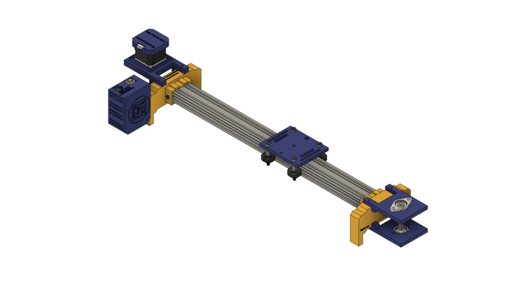
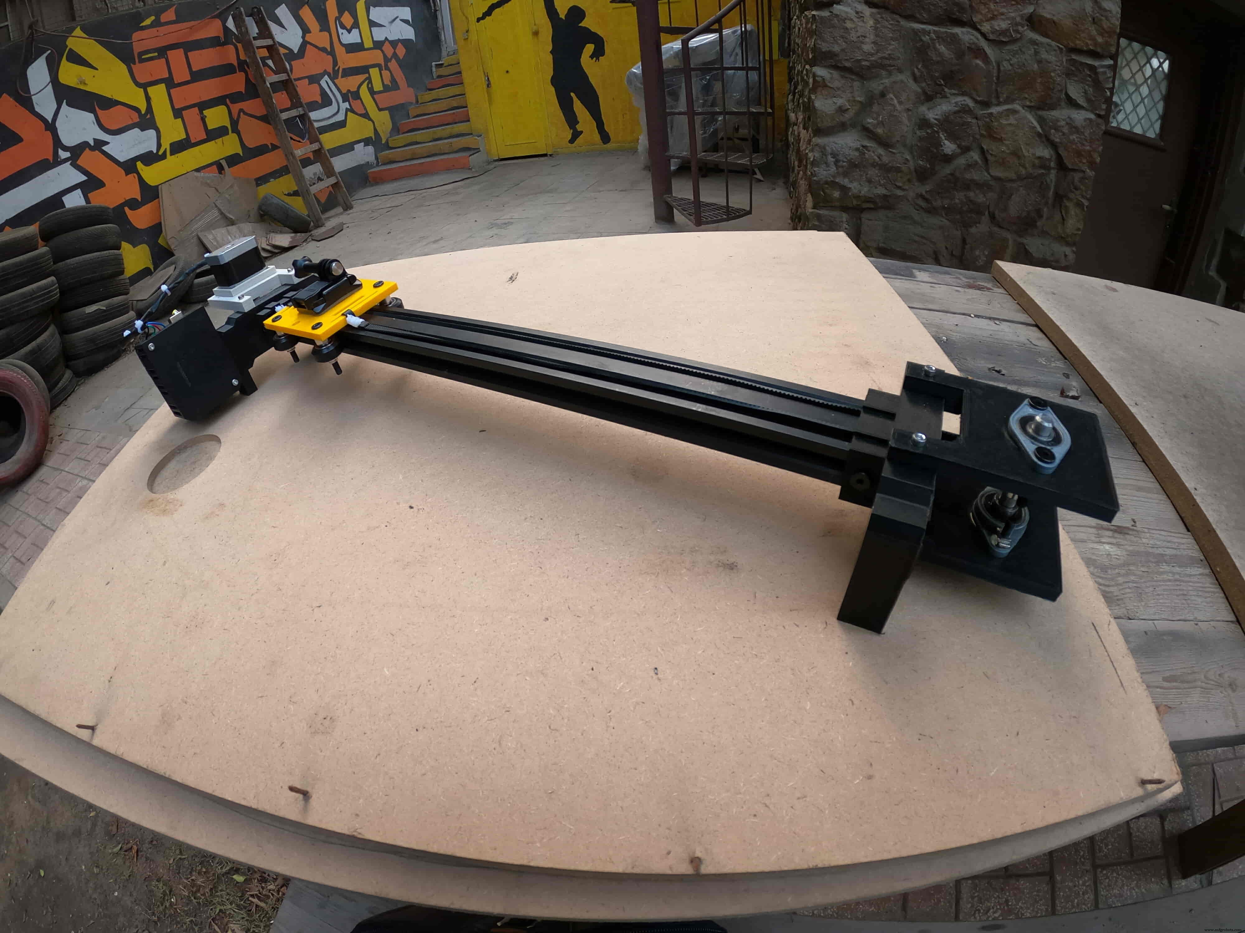
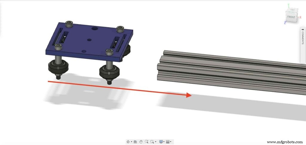
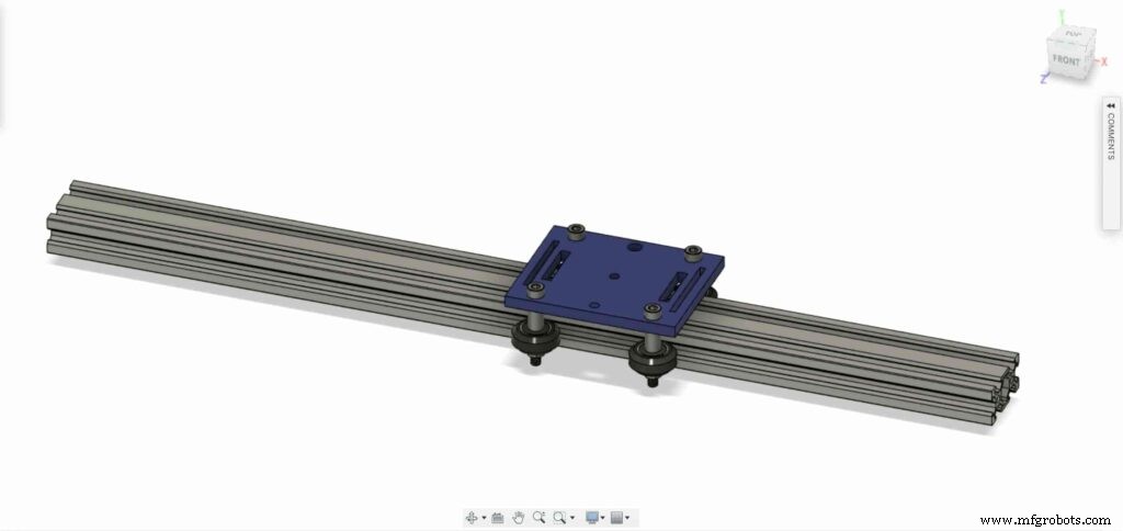
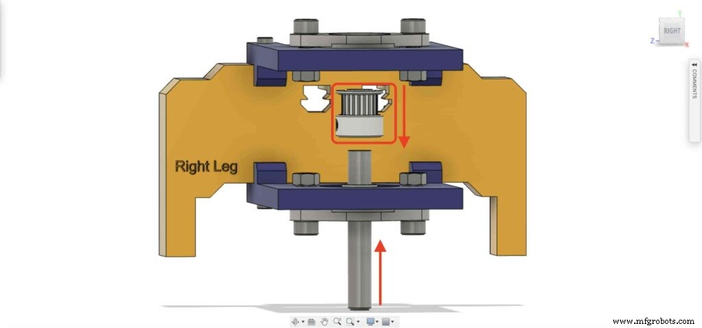
Мы используем оборудование Openbuilds для создания механической конструкции, линейную направляющую V-slot 2040 в качестве направляющей, по которой камера будет двигаться дальше. Два шкива, один на валу шагового двигателя. А другой - на валу линейного рельса диаметром 8 мм на противоположной стороне ползуна с открытым ремнем газораспределительного механизма между ними для преобразования вращательного движения шагового двигателя в линейное движение.
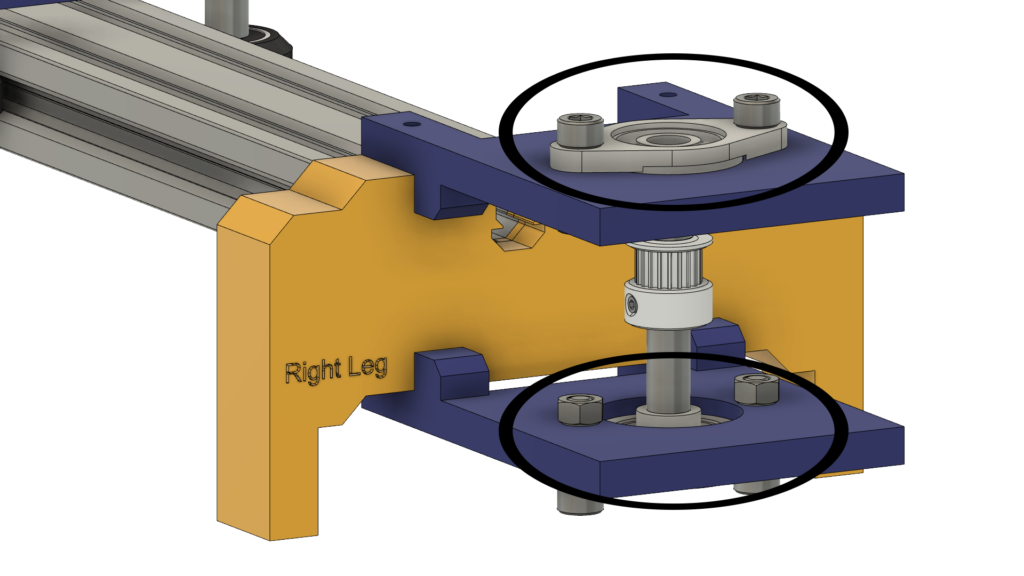
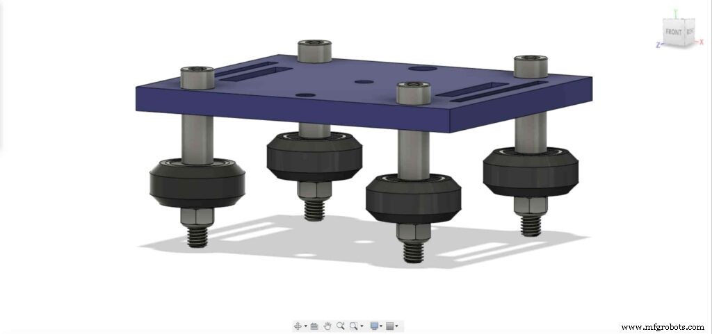
Вал линейного рельса диаметром 8 мм устанавливается между двумя самоустанавливающимися опорными подшипниками с фланцем подушки, которые устанавливаются на верхнюю и нижнюю пластину с помощью четырех винтов M5.
Мы используем четыре сплошных колеса Delrin с V-образным пазом, которые они скользят в V-образной канавке направляющей с V-образным пазом, чтобы сделать движение камеры чрезвычайно плавным. В середине пластины камеры есть отверстие диаметром 1/4 дюйма для стандартного винта штатива, поэтому вы можете легко установить камеру.
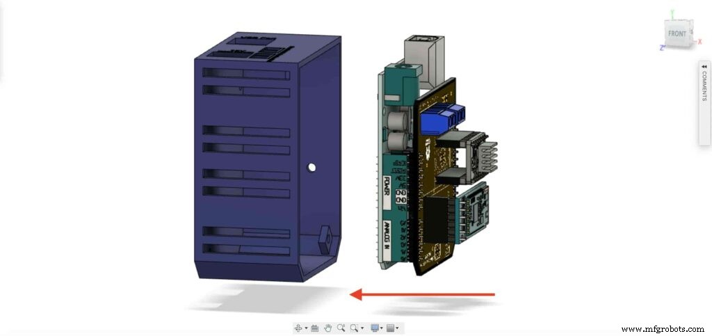
Наконец, корпус для электроники. Все части слайдера камеры крепятся вместе винтами и гайками м3 * 16 мм.
Цифровое производство (3D-печать)
Весь корпус ползунка камеры напечатан на 3D-принтере с высотой слоя 0,2, заполнением 20%, за исключением левой и правой ножки ползунка камеры, напечатан с высотой слоя 0,2 и заполнением 50%.
вы можете скачать файлы STL с Thingiverse.
Сборка V-образного колеса
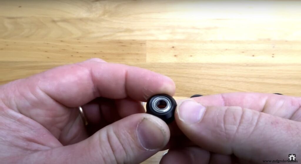
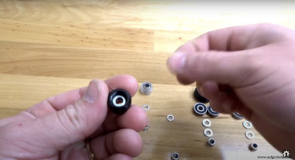
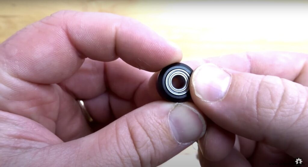
Процесс сборки очень простой человек, давай! На первом этапе нам нужно собрать четыре Solid V-Wheel. В комплект прочного V-образного колеса входит резиновое колесо, два подшипника, две регулировочные прокладки и стопорная гайка.
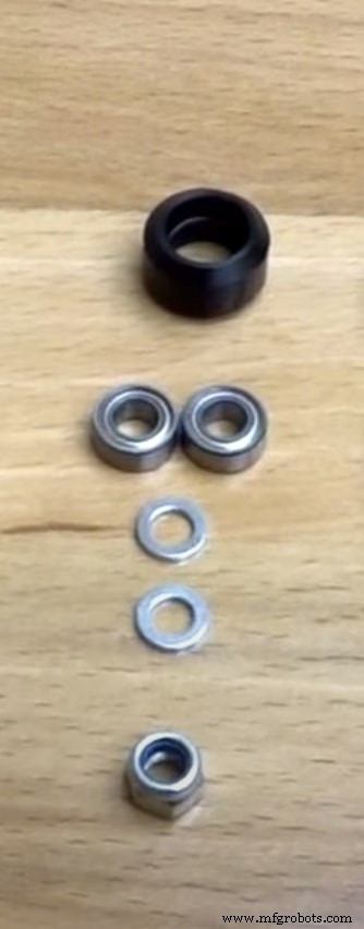
Вставьте подшипник с одной стороны резинового колеса и переверните колесо, затем вставьте одну прецизионную прокладку внутрь резинового колеса, наконец, вставьте второй подшипник со второй лицевой стороны.
Механическая сборка слайдера камеры
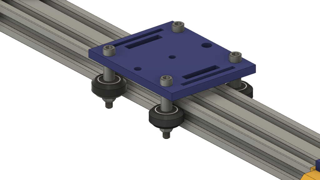
Во-первых, нам нужно собрать пластину камеры и четыре твердых V-образных колеса. используя алюминиевую прокладку 9 мм, прецизионную прокладку и стопорную гайку.

Мы собираемся повторить предыдущий шаг с тремя другими колесами. в двух правых колесах мы будем использовать проставку 9 мм. А для двух других левых колес мы будем использовать эксцентричную распорку с проставкой 3 мм вместо 9 мм.
Теперь вставьте пластину держателя камеры в профиль V-образного паза. Если вы обнаружили, что пластина болтается и качается, вы можете затягивать эксцентриковую гайку, пока не получите прочную пластину.
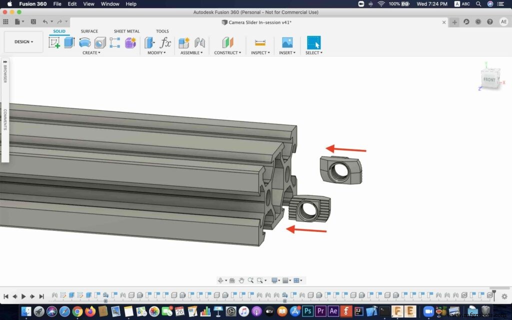
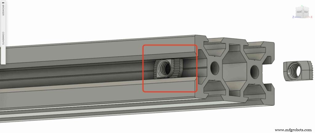
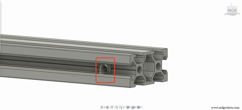
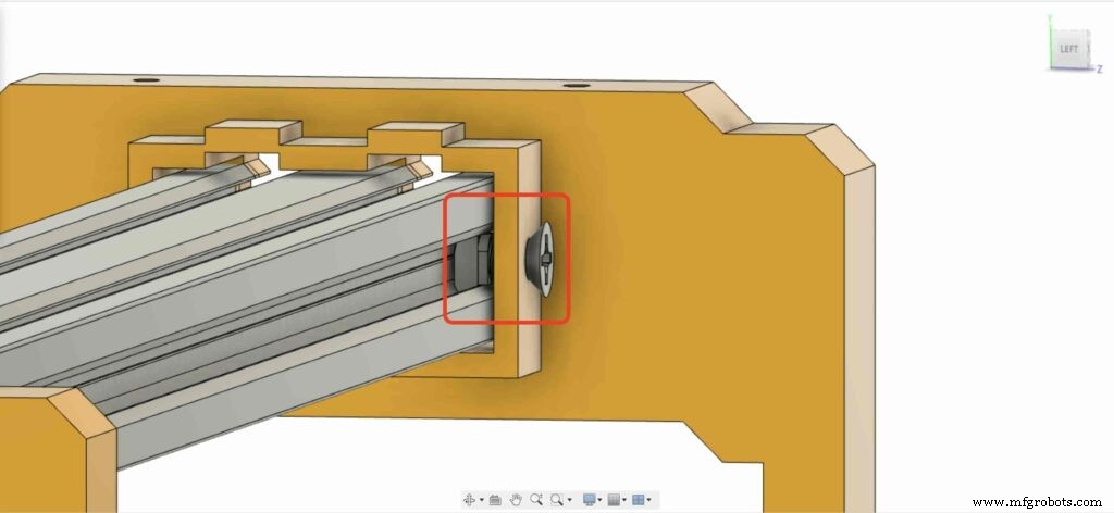
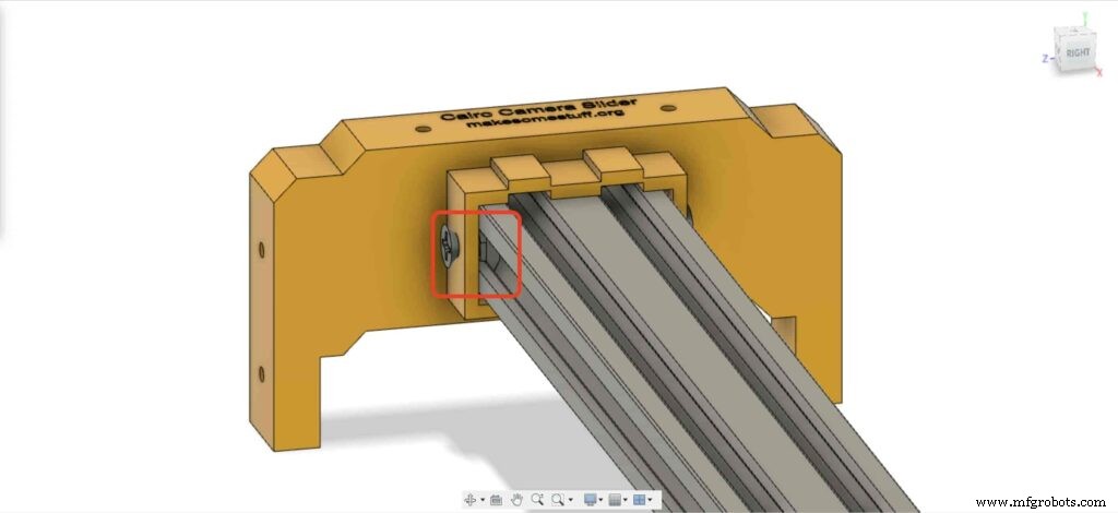
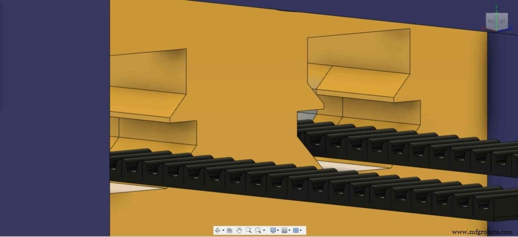
Давайте вставим две тройниковые гайки с каждой стороны профиля с V-образным пазом. нам нужно соединить V-образный профиль с правой и левой ножками слайдера камеры.
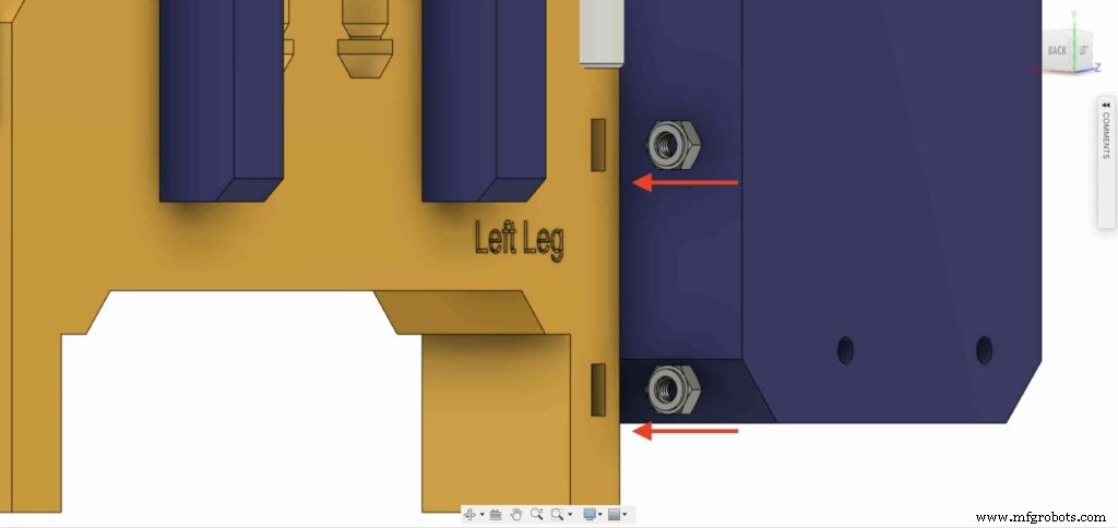
Возьмите две ножки слайдера камеры и вставьте их в профиль V-образного паза.
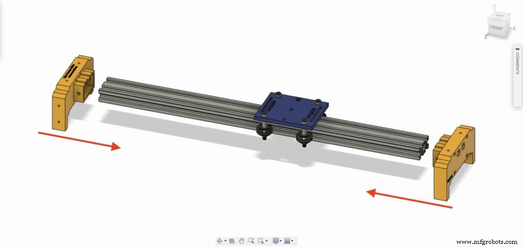

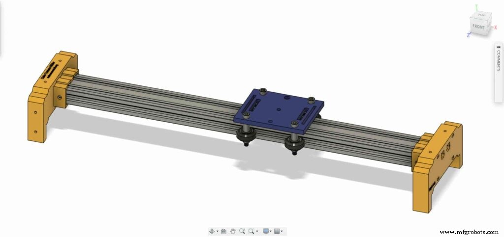
принесите четыре винта M5X10 мм и закрепите две ножки с помощью профиля с V-образным пазом.
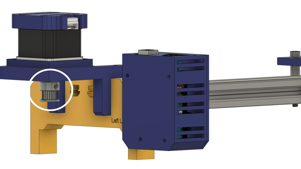
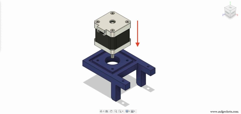
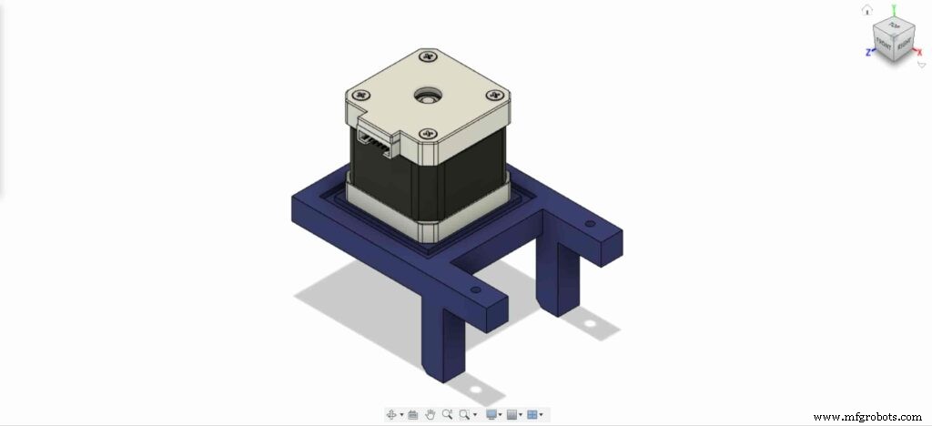
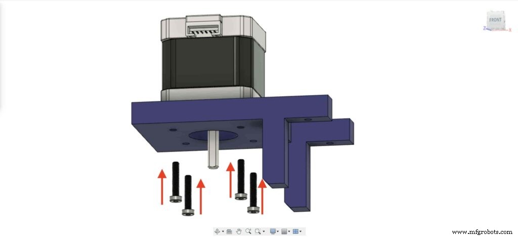
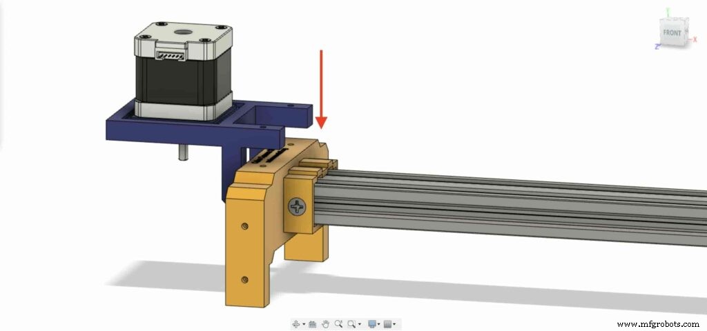
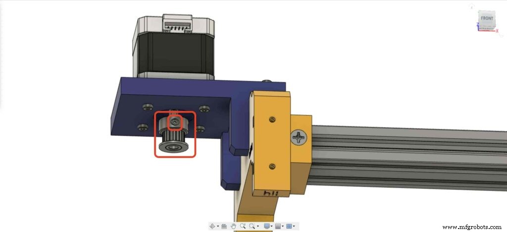
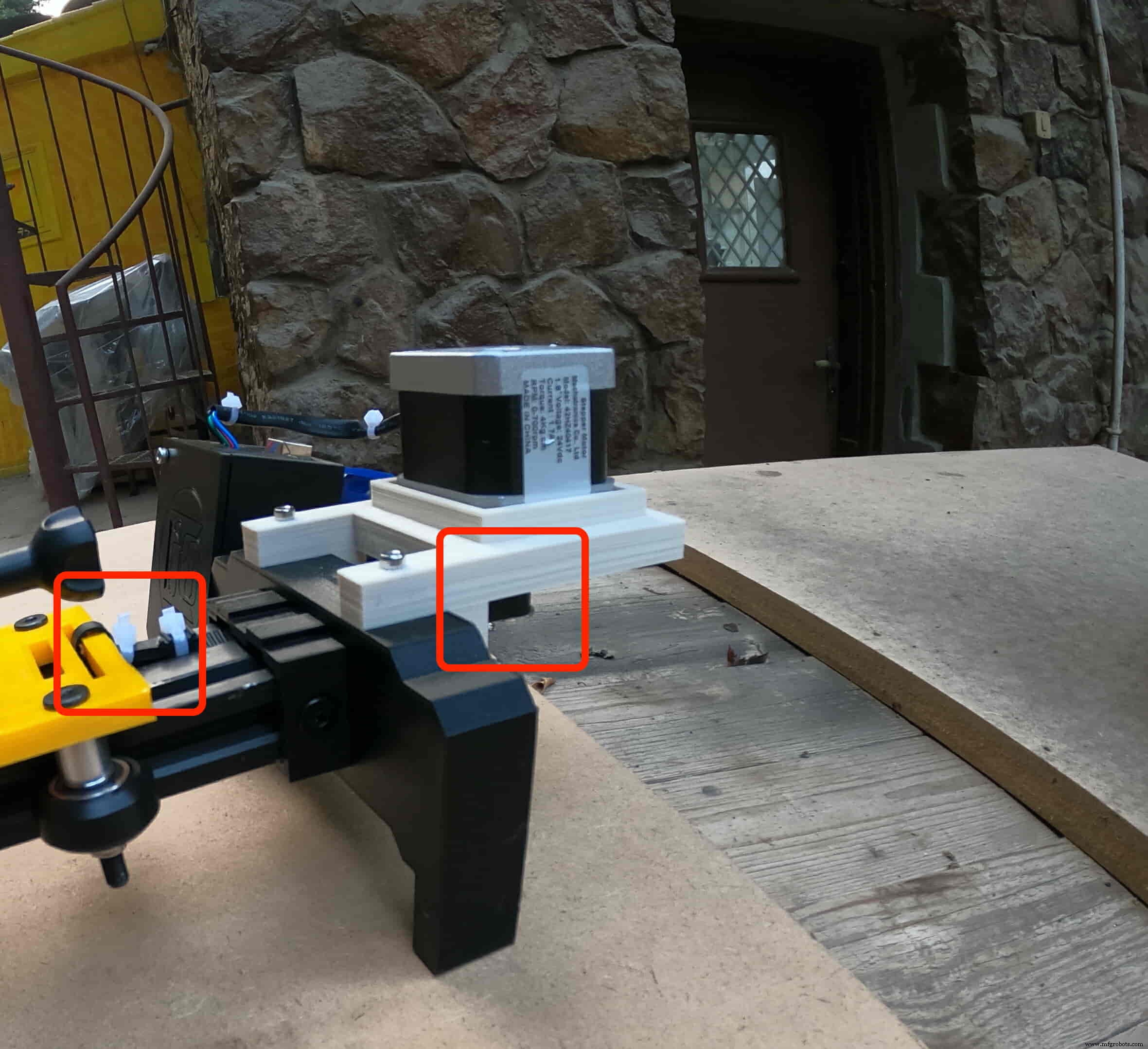
Нам нужно установить на его пластину шаговый двигатель NEMA 17. затем, используя четыре винта M3X16 мм, мы фиксируем двигатель на месте.
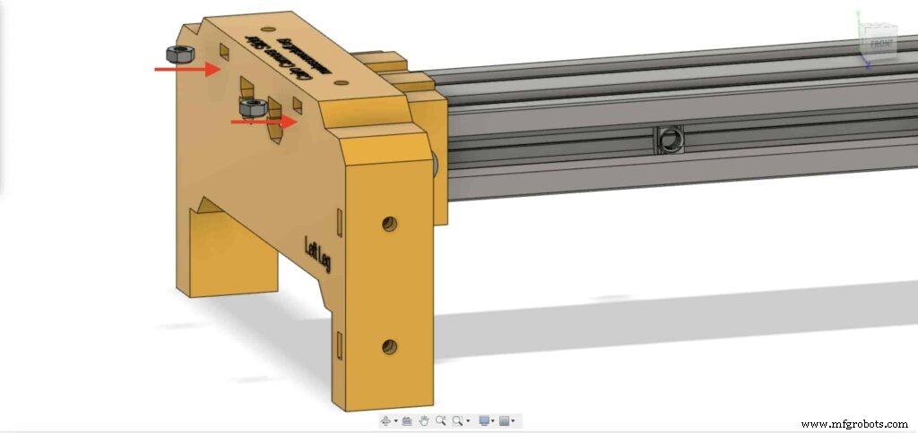
На левой стойке вставьте две гайки в место для верхних гаек левой стойки.
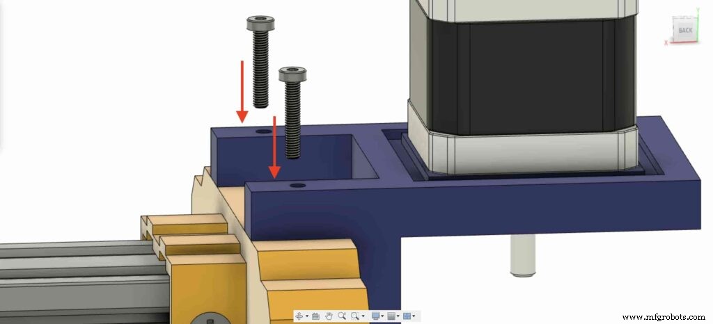
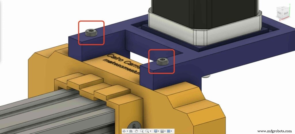
Принесите пластину двигателя NEMA 17 и закрепите ее на верхней части левой ноги. и, используя два винта M3X16mm, закрепим пластину на левой ножке.
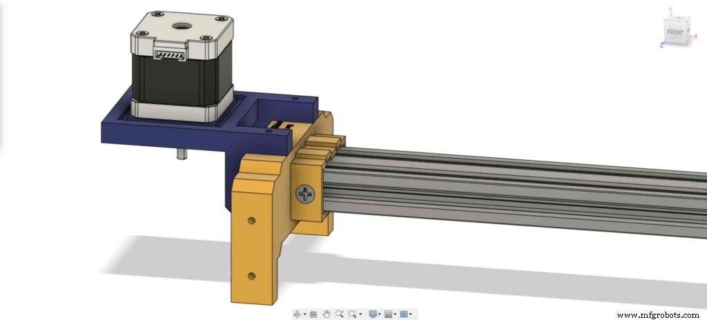
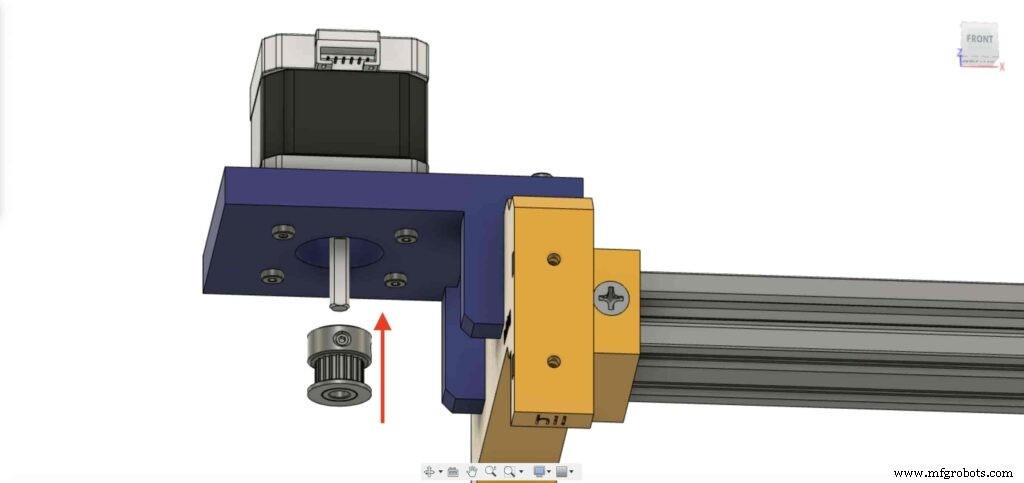
Чтобы иметь возможность преобразовать вращательное движение шагового двигателя в линейное движение, нам необходимо установить шкив GT2 диаметром 5 мм на валу двигателя. и с помощью шестигранного ключа затяните установочный винт шкива, чтобы он оставался на месте.
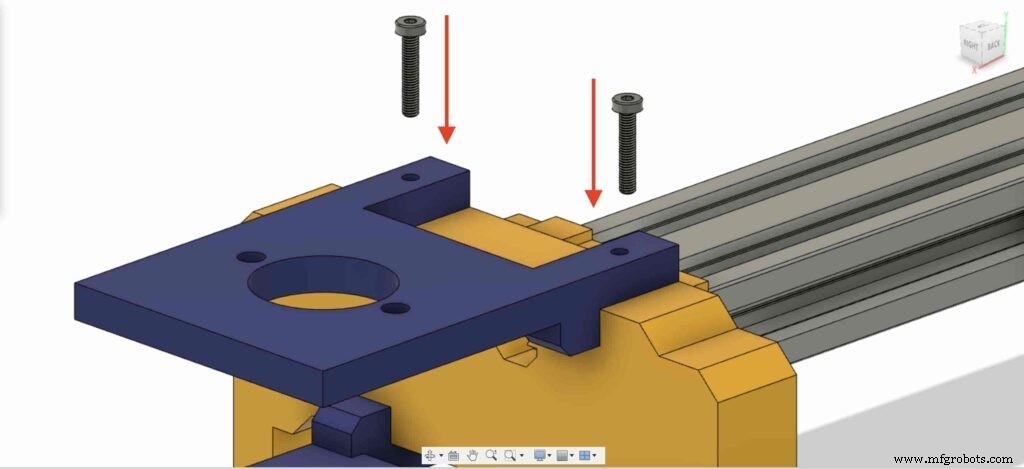
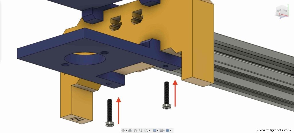
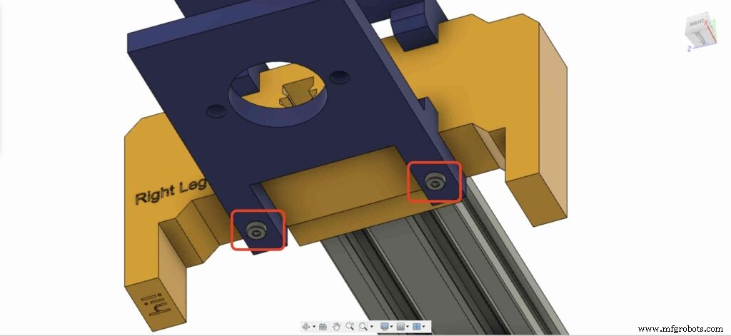
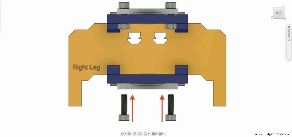
Переходим к правой ножке слайдера камеры, вставляем четыре гайки M3 в место гаек.
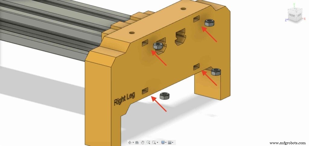
Затем поместите две пластины подшипника правой ноги на верхнюю часть правой стойки ползунка камеры.
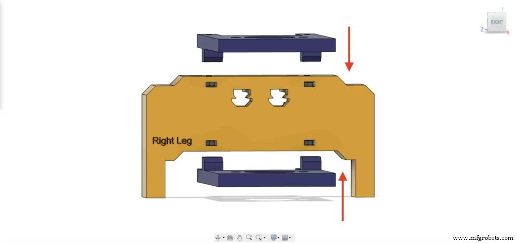
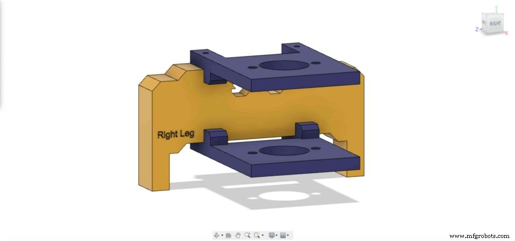
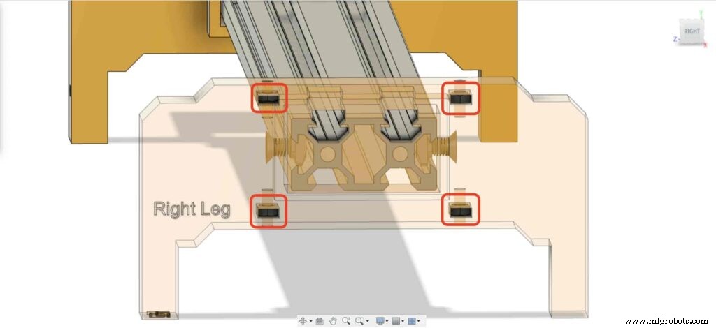
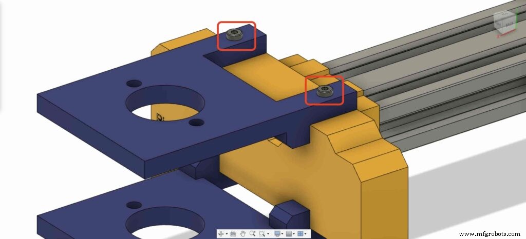
С помощью четырех винтов M3X16 мм закрепите две пластины на правой ножке ползунка камеры, чтобы они оставались на месте.
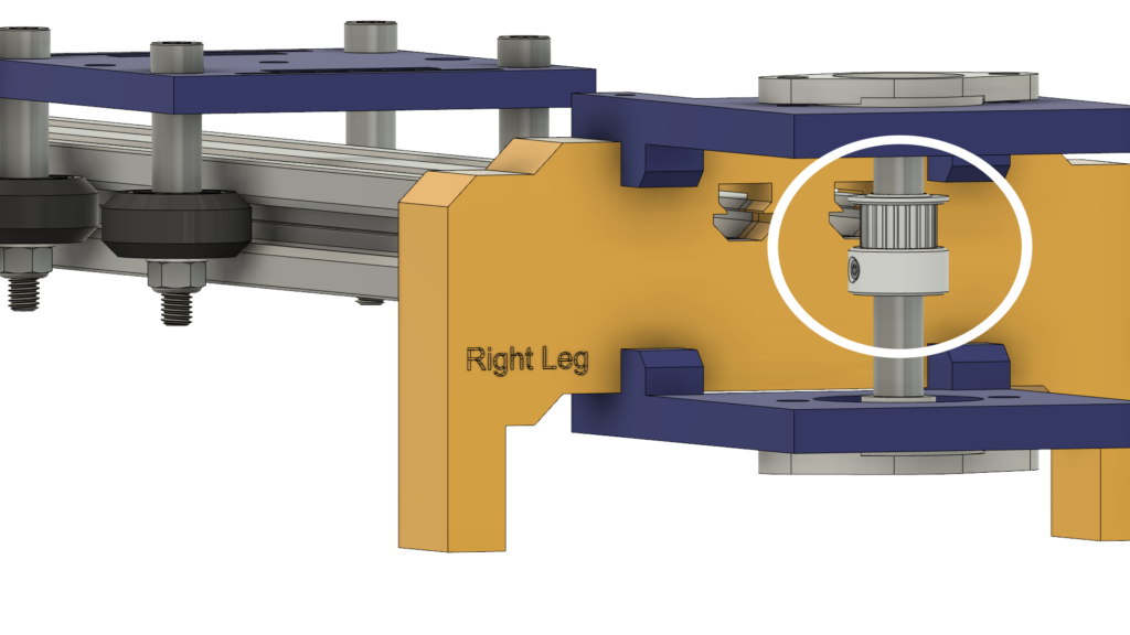
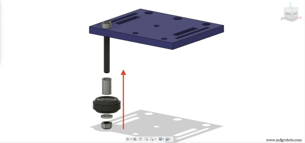
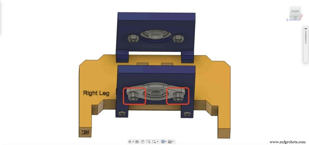
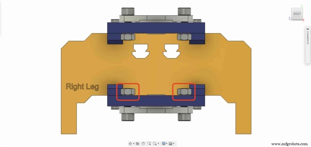
Принесите один из 8-миллиметровых подшипников фланцевого блока и установите его на верхнюю правую опорную пластину. используя два винта M5X20 мм и две гайки M5.
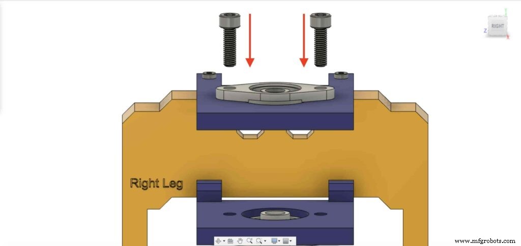
Нам нужно повторить предыдущий шаг со вторым 8-миллиметровым фланцевым подшипниковым блоком, чтобы закрепить его на нижней пластине правой ножки ползунка камеры.
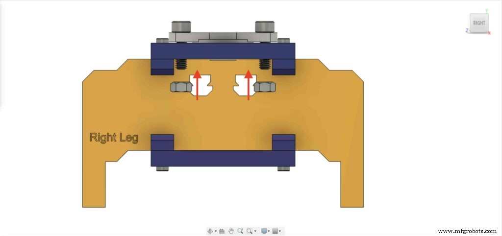
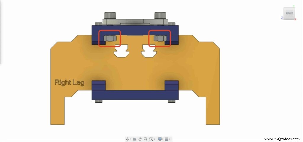
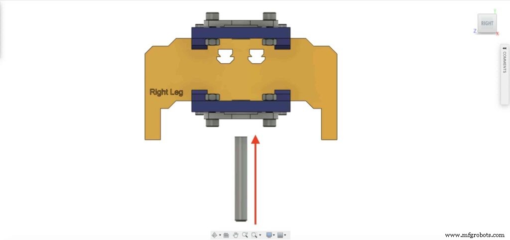
Вставьте 8-миллиметровый вал линейного рельса в 8-миллиметровый опорный подшипник с фланцем с его нижней стороны и надавите на него вверх. Затем вставьте шкив с отверстием 8 мм в вал линейного рельса и закрепите его, затянув установочный винт шкива.
Checkpoint, Сейчас мы собрали весь механизм слайдера камеры кроме одного. ремень ГРМ. Давай сделаем это.
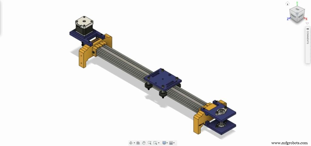
поверните 6-миллиметровый ремень ГРМ на шкиве двигателя NEMA17 с диаметром отверстия 5 мм. Также на правой ноге расточка шкива 8мм. Наконец, затяните ремень с пластиной камеры.
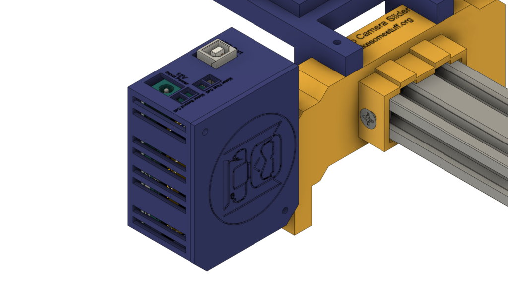
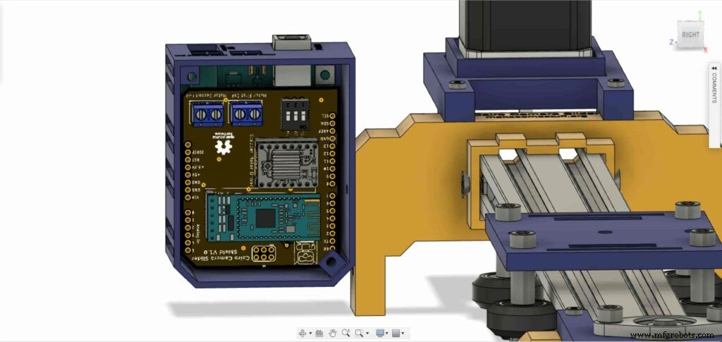
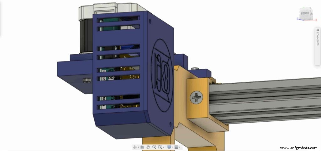
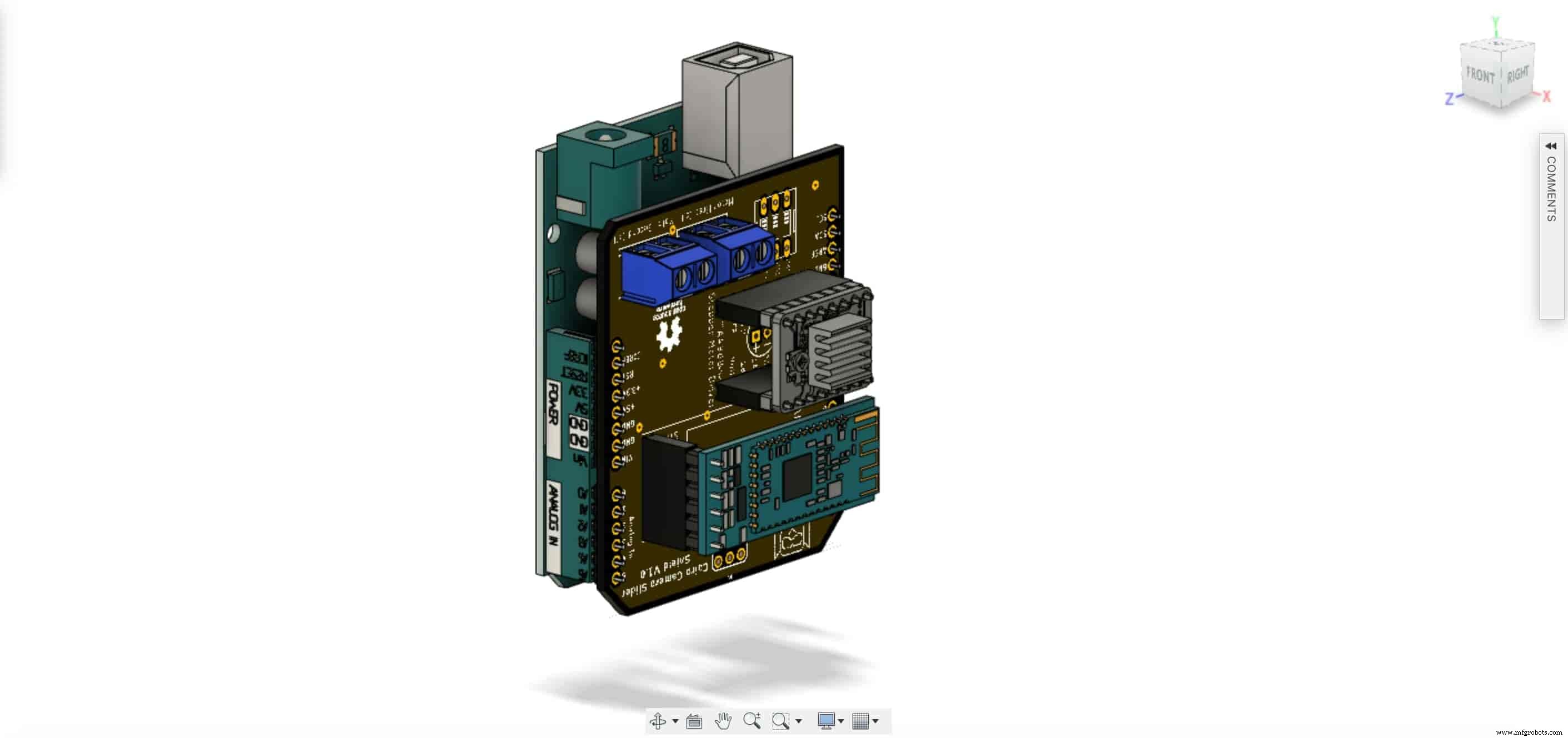
Пришло время собрать плату управления. вставьте экран Cairo Camera Slider Arduino в верхнюю часть платы Arduino.
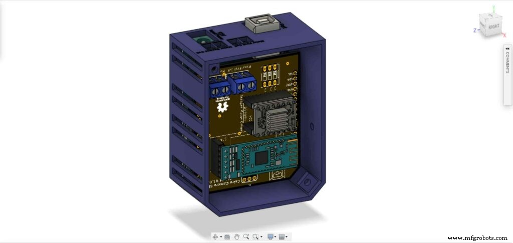
Вставьте плату Arduino и экран Cairo Camera Slider в корпус платы управления.
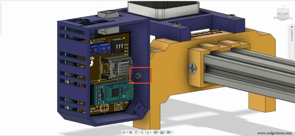
вставьте две гайки M3 в место для гаек левой стойки.
Установите корпус платы управления на левую ножку Cairo Camera Slider с помощью винтов M3X16 мм.

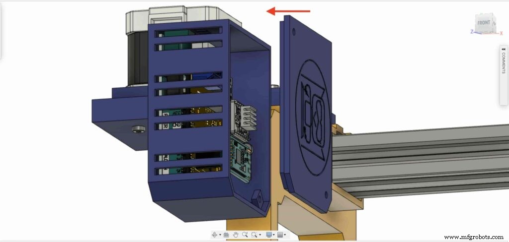
закройте верхнюю часть корпуса корпуса двумя винтами и гайками M3, и все!

Управление тестированием шагового двигателя
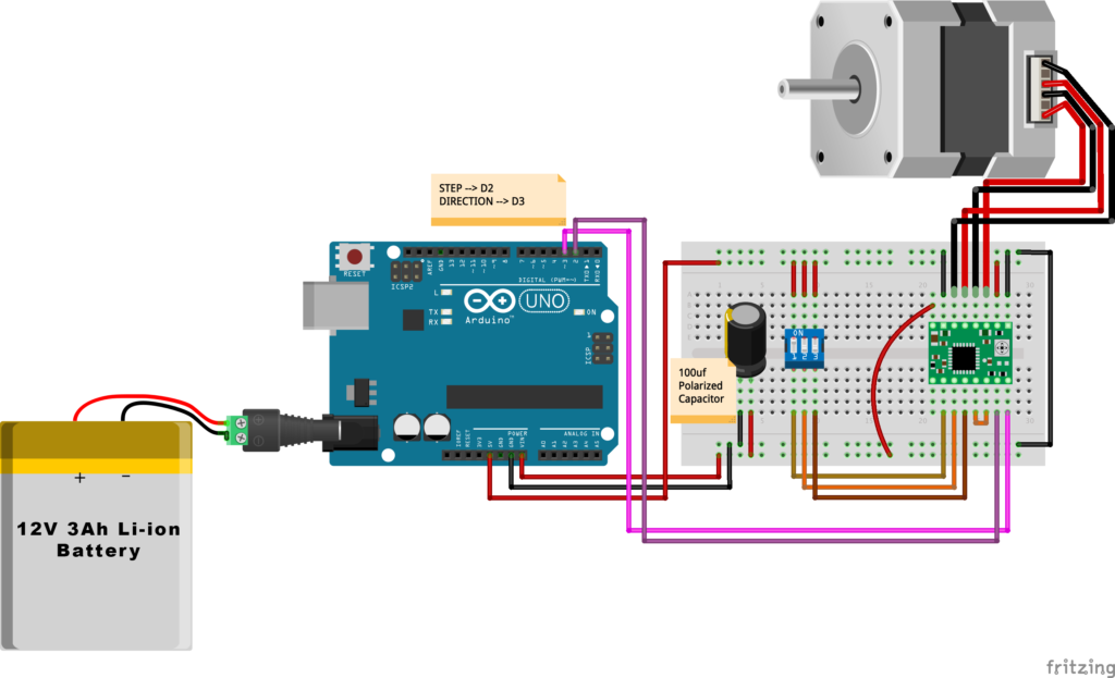
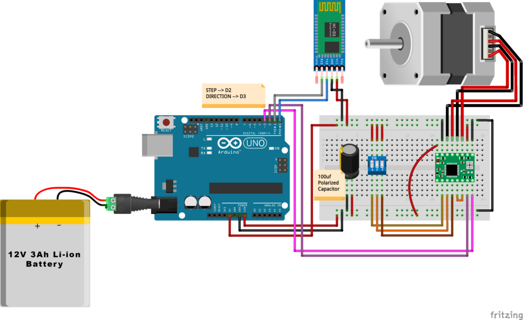
Собрав все детали вместе, нам нужно протестировать его, чтобы убедиться, что все правильно установлено на свои места. Now, we need to connect the stepper motor with the Arduino board through the A4988 stepper motor driver and write some code to run that thing.
A4988 stepper motor driver
To control any stepper motor using the Arduino board or any microcontroller, you will need a stepper motor driver which works as a translator, takes commands from the Arduino board and translate it to the language that the motor understands.
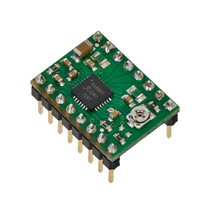
there are a lot of stepper motor drivers out there but we will use the A4988 driver . This driver allows us to control one bipolar motor at up to 2A output current per coil, it’s very simple to interface with the Arduino board you only need two digital pins to fully control your motor step and direction, allows you to control the maximum current output easily with an onboard potentiometer, and gives you a micro-step resolution down to 1/16 micro-step.
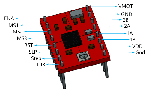
VMOT, GND: It’s the power connection pins for the stepper motor itself, it can be 8V-35V. In our case, we are connecting a 12V 3A power source on those pins with a 100uf decoupling capacitor to protect the A4998 board from any power spikes.
2B, 2A: the output pins for the stepper motor first coil which can deliver up to 2A.
1A, 1B: the output pins for the stepper motor second coil which can deliver up to 2A as well.
VDD, GND: Used for driving the internal logic circuitry, it can be 3V to 5.5V. It’s totally isolated from the VMOT pin.
EN: Stands for “Enable” it’s an active LOW(0V) input pin, which means when this pin pulled LOW(0V) the A4988 chip is enabled. And when pulled HIGH(5V) the A4988 chip is disabled. By default, this pin is pulled LOW(0V). So, the chip is always enabled unless you pull it HIGH(5V).
MS1, MS2, MS3: Through these pins, you can select your motor microstepping resolution(step size). The A4988 gives you five different microstep resolutions (full step, half step, quarter step, Eighth step, Sixteenth step) . By applying appropriate logic levels to these three pins we can set the motors to one of the five step resolutions.
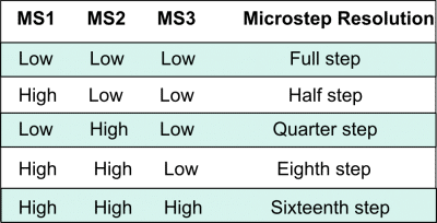
By default, the MS1, MS2, MS3 pins have internal pull-down resistors. So leaving these three microstep selection pins disconnected results in full-step mode.
RST, SLP: The “Reset” pin is an active LOW(0V) input pin, which means when it pulled LOW(0V), all the step inputs are ignored it also resets the translator itself until you pull it HIGH(5V). The “Sleep” pin also an active LOW pin, pulling it LOW, puts the driver in the sleep mode minimizing the power consumption. By default, the “Sleep” pin is pulled HIGH(5V).
STP, DIR: The “Step” pin is responsible for controlling the number of steps that the motor is rotating, each pulse to the “Step” pin corresponds for one microstep in the direction selected by the “Direction” pin, the faster the pulses, the faster the motor will rotate. By applying logic value HIGH(5V) on the “Direction” pin it makes the motor rotate clockwise, by applying LOW(0V) it makes the motor rotate counterclockwise(it may differs from one to another according to your motor wiring with the driver).
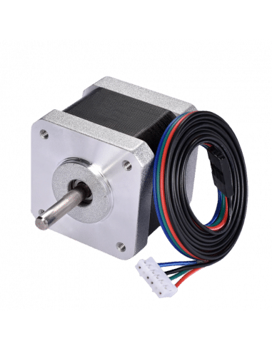
NEMA17 Stepper Motor
Stepper motors are DC motors that can rotate in precise increments, they are used in many applications like 3D printers to align the printhead and CNC machines to control the movement of the cutting tool and this is because they are very accurate and precise.
Unlike DC motors, stepper motors are controlled by applying DC electrical pulses to their internal coils. Each pulse makes the shaft advance by one step or a fraction of step which is called “Microstepping”. So, you can control precisely how many steps or even fraction steps you want the motor shaft to move. Another great advantage of using stepper motors is that it can move very precisely and accurately at very slow speeds without even stalling.
The type of motor we are using in this project is the NEMA 17 Bipolar stepper motor . The bipolar stepper motor has two internal coils and it usually has four wires, two wires per coil. unlike the Bipolar stepper motor which has five wires. The “Step Angle” of the motor is 1.8° which indicates how much the shaft advances in each full step, the motor works on 9V but if you want to get the maximum power of it use a 12V power source.
So, by connecting the stepper motor with the A4988 stepper motor driver, we can control how many steps we need the motor to move and in what direction. Also, we can set the “microstep” mode is it full step, half step, quarter step, ….. Let’s take a look at the wiring diagram.
Wiring Diagram
As we stated before, we need to make a small check to make sure that everything we assembled before is right in its place and moving properly. Now, we will wire all the hardware together, the NEMA 17 stepper motor with the A4988 stepper motor driver to the brain, the Arduino board. And using a 12V 3A Lithium-Ion battery to feed the motors with the power it needs.
Arduino Code
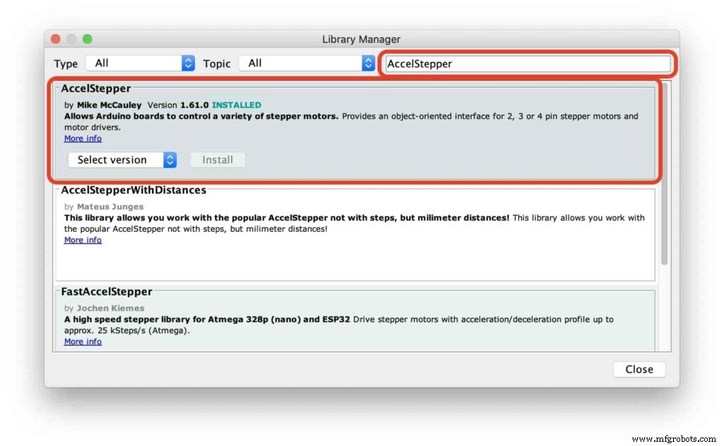
AccelStepper Library Installation
The Installation is pretty simple, we need to open Arduino IDE. From the “Sketch” menu. Select Include Library –> Manage Libraries…
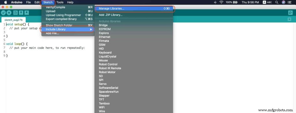
A new window should appear, search for “AccelStepper” and install the library made by “Mike McCauley”. Easy right!
After installing the AccelStepper library, you should see it in the examples menu.
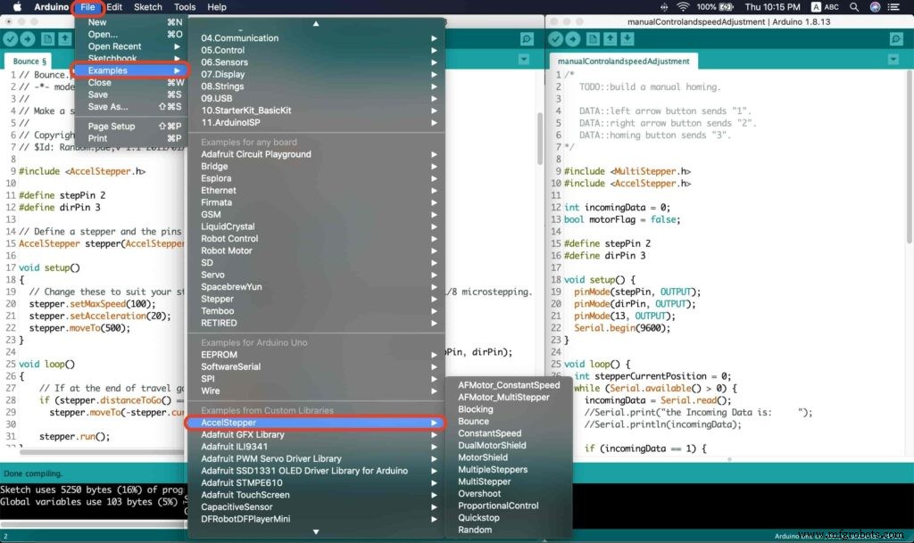
I wanna make sure that the AccelStepper library is installed correctly and my stepper motor connection with the A4988 motor driver is right and my power management is fine. So, let’s write some lines of code to run our stepper motor forward and backward.
// Bounce stepper test program
// Make a single stepper bounce from one limit to another
// Copyright (C) 2020 makesomestuff.org

#include
#define stepPin 2
#define dirPin 3 // Define a stepper and the pins it will use

AccelStepper stepper(AccelStepper::DRIVER, stepPin, dirPin); //create an object. the pin "2" is the step pin, "3" is the direction pin.

void setup()
{
 // Change these to suit your stepper if you want
 stepper.setMaxSpeed(100);
 stepper.setAcceleration(20);
 stepper.moveTo(500);
}

void loop()
{
 // If at the end of travel go to the other end
 if (stepper.distanceToGo() ==0)
 stepper.moveTo(-stepper.currentPosition());
 stepper.run();
}
The code logic is pretty straightforward, we initialized an object from the AccelStepper library, we defined two constants (stepPin, dirPin) that two digital pins is used by the A4988 stepper motor driver to control the movement of the motor itself.
#include

#define stepPin 2
#define dirPin 3 // Define a stepper and the pins it will use

AccelStepper stepper(AccelStepper::DRIVER, stepPin, dirPin); //create an object. the pin "2" is the step pin, "3" is the direction pin.
Inside the void setup function, we set the Max. speed of the stepper motor to 100 steps/sec. Also, we set the acceleration/deceleration rate to 20 steps/sec. lastly, we used the moveTo() function to tell the motor to move 500 steps.
void setup()
{
 // Change these to suit your stepper if you want
 stepper.setMaxSpeed(100);
 stepper.setAcceleration(20);
 stepper.moveTo(500);
}
Inside the void loop function, we are checking if the motor reached it’s position or not. If it reached the position, it will bounce back. and if it didn’t reach it’s position yet, it will keep running.
void loop()
{
 // If at the end of travel go to the other end
 if (stepper.distanceToGo() ==0)
 stepper.moveTo(-stepper.currentPosition());
 stepper.run();
}
Camera Slider Full Wireless Control
We have done great things so far. Let’s continue! The next step after testing everything, is to work on the mobile app that we will use to control the camera slider movement and send the orders to it. Also, we need to work on the Arduino code that will receive the data from the mobile app and according to these data it will take some actions like moving the motor, changing speed, acceleration, and so on…
Building The Mobile App
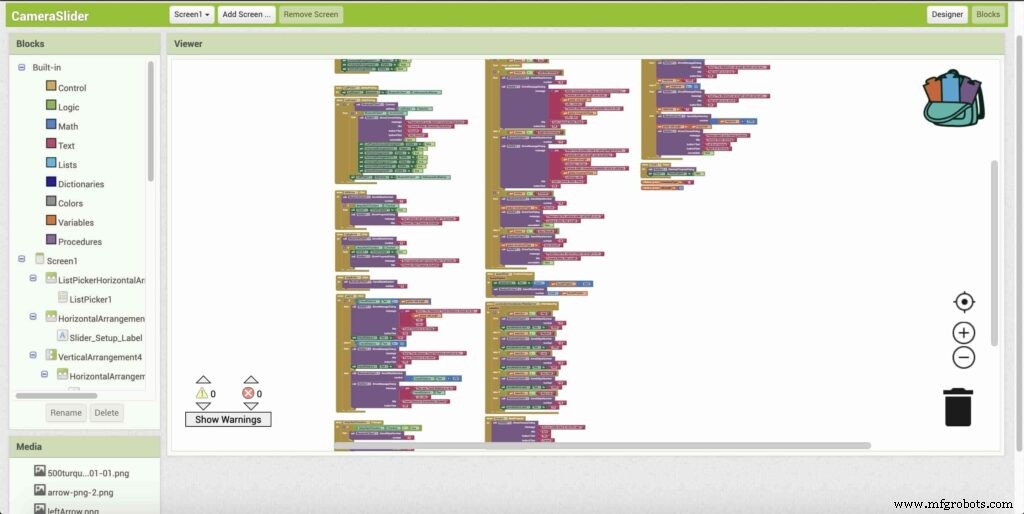
To build the mobile app, I used the MIT App inventor tool that allows you to create mobile apps that run on any Android smartphone. The tool is pretty simple since you only drag and drop some pre-made code blocks to build the logic of your program, also you use some premade blocks to build the app user interface. You can access the source of the mobile app from the link down below. Feel free to edit and share, it’s open-source. Mobile App Source
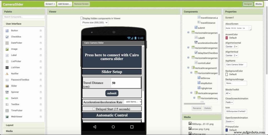
The image down below, a brief explanation for each button function and how it works.
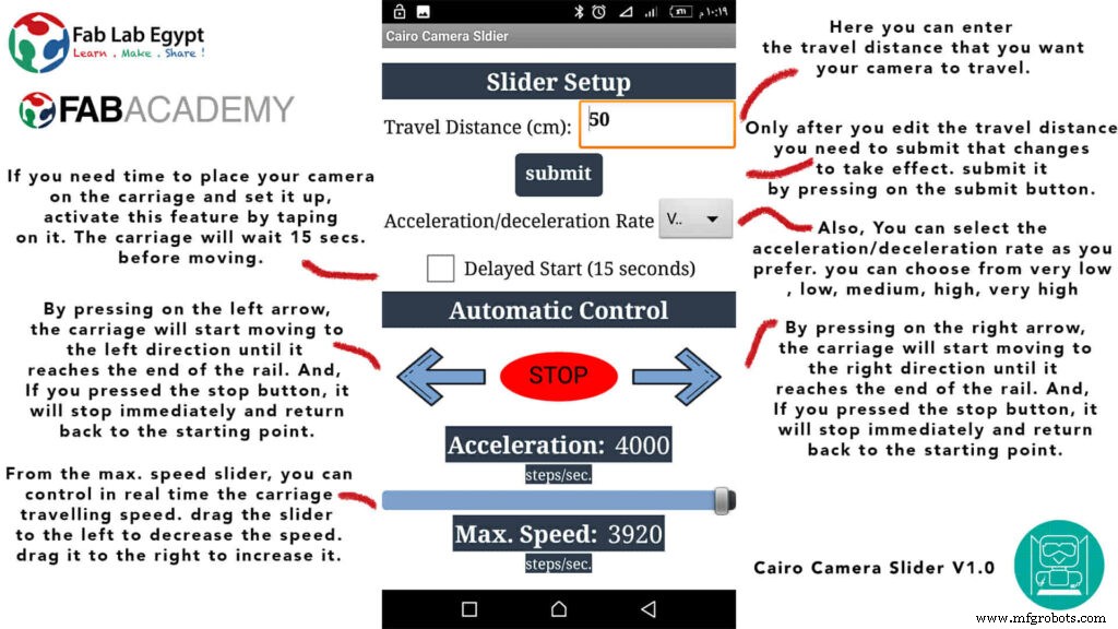
That mobile app will communicate with the Cairo camera slider wirelessly over the Bluetooth communication. So, the next step is to connect a Bluetooth module to the last circuit we built before and upload some lines of code to the Arduino board to be able to establish the communication between the mobile app and the Cairo camera slider.
Wiring Diagram
It’s the time to connect all things together, previously we connected the stepper motor, stepper motor driver, Arduino UNO, and the battery together and tested the circuit and it worked fine. Now, and after building the mobile app, we need to connect the HC-05 Bluetooth module to our circuit.
To make it wireless we will use the HC-05 Bluetooth module which has wide use, it can set as slave or master as well (unlike the HC-06 module which can work only as a slave) which means that you can make a Bluetooth connection between two different Arduino boards. the HC-05 Bluetooth module is an SPP (Serial Port Protocol) module, which means that it communicates with the Arduino board via the Serial communication. You only need to connect the Tx and the Rx pins between the HC-05 module and the Arduino UNO board.
- Tx(Arduino) --> Rx(HC-05)
- Rx(Arduino) --> Tx(HC-05)
- 5V(Arduino) --> VCC(HC-05)
- GNND(Arduino) --> GND(HC-05)
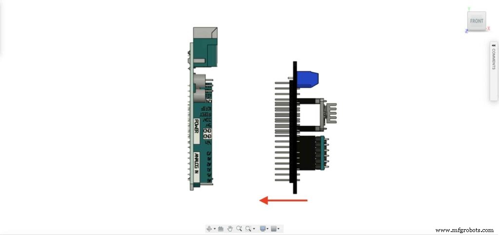
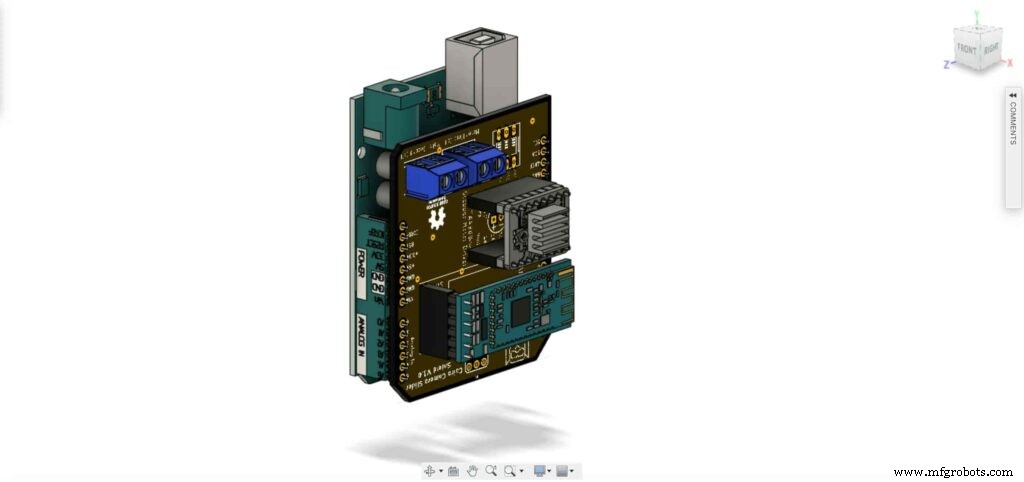
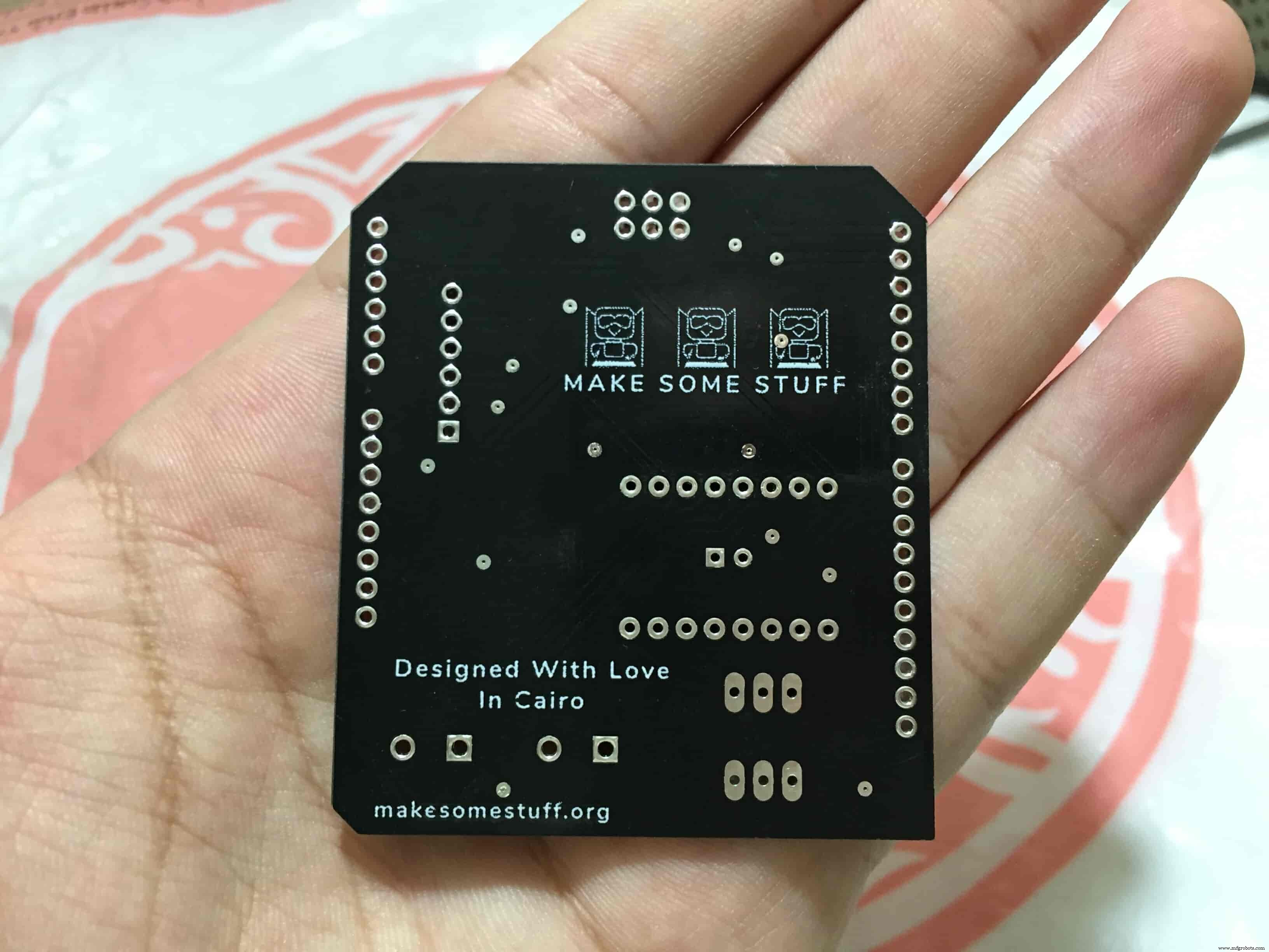
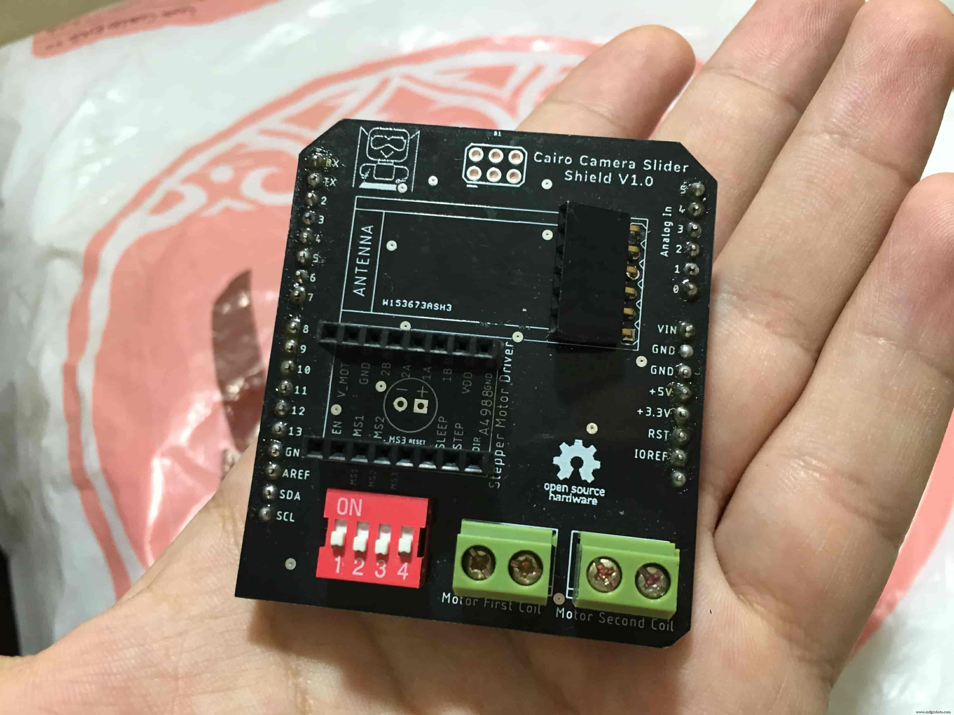
Schematic and PCB Fabrication
Мужчина! I don’t like breadboarding a big circuit like this. So, I designed a super pretty Arduino UNO shield PCB board that keeps all my components in place without worrying about the jumper wires or even the connections. All you need to do is to place your component on the Arduino shield PCB, insert the HC-05 Bluetooth module, A4988 stepper motor driver, and the battery in their places. and install the shield on top of the Arduino board. that’s it!
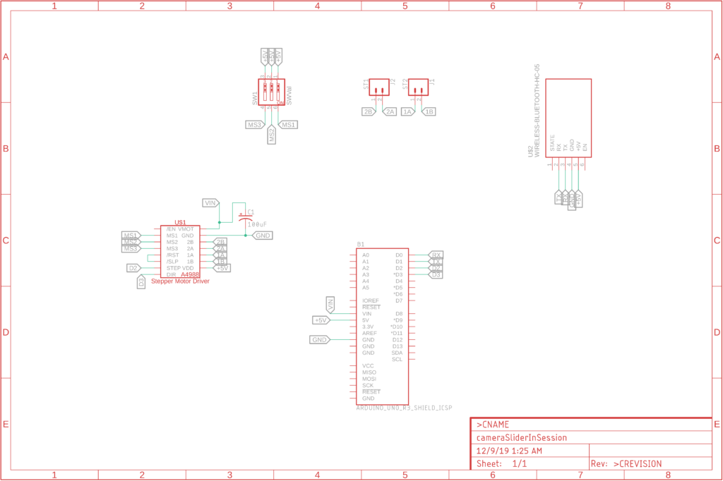
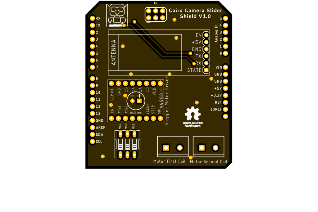
I fabricated my PCB at PCBWay the quality was very good, in a few days the package arrived in Egypt safely. and I paid just 5$ for the fabrication which is amazing. The coolest thing that I was able to check the order fabrication and processing status online on my account panel and track everything happening to my baby board like I was there inside the factory.
you can download the PCB design source files or even ordering the Cairo Camera Slider Arduino Shield PCB from the PCBWay website. PCB Source Files &Ordering

Arduino Code And Bluetooth Communication
/*
 TODO::Update the arduino program to Make the user able to choose the motor driver micro stepping mode. find and equation that helps to automatically adjust the the "steps" variable value.
 TODO::update the mobile app to ask the user on the beginning only about the [homing position(done), microstepping mode].
 TODO::Update the arduino program to make the code only iterates around the "homing position" &"microstepping mode" only once on the void setup() function.

 DATA::left arrow button sends --> 1.
 DATA::right arrow button sends --> 2.
 DATA::stop button sends --> 3.

 DATA::rail length (1cm - 1000cm) --> (201 - 1200).

 DATA::motor acceleration spinner Very High --> 14.
 DATA::motor acceleration spinner High --> 11
 DATA::motor acceleration spinner Medium --> 12
 DATA::motor acceleration spinner Low --> 13
 DATA::motor acceleration spinner Very Low --> 15

 DATA::motor speed slider (1 step/sec. - 4000 step/sec.) --> (5001 - 9000).

 DATA::delay start checkbox is true --> 7.
 DATA::delay start checkbox is false --> 8.

 DATA::left end homing --> 16.
 DATA::right end homing --> 17.

 DATA::Smooth movement Type --> 18.
 DATA::Very Smooth movement Type --> 19.

 1301 --> 2300
*/

#include
#include

#define stepPin 2
#define dirPin 3

bool homingPositionFlag =false;
int startupSetupFlag =0;
bool delayedStart =false;

int incomingData =0;
int movementDistance =50;
long steps =0; //50cm rail by default @1/8 microstepping.
int microStepResolution =0; //4 or 16
long railLength =0;
int sliderSpeed =10;

AccelStepper stepper(AccelStepper::DRIVER, stepPin, dirPin); //create an object. the pin "2" is the step pin, "3" is the direction pin.

void setup() {
 pinMode(stepPin, OUTPUT);
 pinMode(dirPin, OUTPUT);
 Serial.begin(9600);

 stepper.setMaxSpeed(10.00); //The fastest motor speed that can be reliably supported is about 4000 steps per second at a clock frequency of 16 MHz on Arduino such as Uno
 stepper.setAcceleration(500.00); //1600 (40%) (Medium Acceleration rate)

 while (startupSetupFlag <3) {
 if (Serial.available()> 1) {
 unsigned int dataOne =Serial.read();
 unsigned int dataOne1 =Serial.read();
 unsigned int incomingData =(dataOne1 * 256) + dataOne;

 //**************************************************************Motor Homing Part**************************************************
 if (incomingData ==16) { //left end homing position.
 stepper.setCurrentPosition(steps);
 homingPositionFlag =false;
 startupSetupFlag++;
 } else if (incomingData ==17) { //right end homing position.
 stepper.setCurrentPosition(-(steps));
 homingPositionFlag =true;
 startupSetupFlag++;
 }
 //**************************************************************microstep resolution Part**************************************************
 if (incomingData ==18) {
 microStepResolution =4; //50cm rail length @1/4 microstep resolution.
 startupSetupFlag++;
 } else if (incomingData ==19) {
 microStepResolution =16; //50cm rail length @1/16 microstep resolution.
 startupSetupFlag++;
 }

 if (incomingData>=1301 &&incomingData <=2300) {
 railLength =incomingData - 1300; //from raw data to cm.
 if (microStepResolution ==4) {
 steps =((6100L * railLength) / 50L);
 startupSetupFlag++;
 }
 else if (microStepResolution ==16) {
 steps =((25000L * railLength) / 50L);
 startupSetupFlag++;
 }
 }
 }
 //Serial.println(startupSetupFlag);
 }
 /*
 * *********** *********** **********For Debugging Purposes* *********** *********** **********
 Serial.print("rail length:");
 Serial.print(railLength);
 Serial.print(" number of steps:");
 Serial.print(steps);
 Serial.print(" Homing position:");
 Serial.print(stepper.currentPosition());
 Serial.print(" microstep resolution:");
 Serial.println(microStepResolution);*/
}

void loop() {

 if (Serial.available()> 1) {

 unsigned int dataOne =Serial.read();
 unsigned int dataOne1 =Serial.read();
 unsigned int incomingData =(dataOne1 * 256) + dataOne;
 //Serial.print("raw data:");
 //Serial.println(incomingData);

 //**************************************************************Motor Control Part**************************************************
 if (incomingData ==1 &&stepper.isRunning() ==false &&stepper.currentPosition() !=6050 &&homingPositionFlag ==true) {
 if (delayedStart ==true) { //use millis to delay 15 seconds.
 delay(15000); //wait 15 seconds.
 }
 stepper.setCurrentPosition(0);
 stepper.moveTo(steps); //from end to end (@ 1/4 step).
 homingPositionFlag =false;

 /*Serial.print("rail length:");
 Serial.print(railLength);
 Serial.print(" number of steps:");
 Serial.print(steps);
 Serial.print(" Homing position:");
 Serial.print(stepper.currentPosition());
 Serial.print(" microstep resolution:");
 Serial.println(microStepResolution);*/
 }

 else if (incomingData ==2 &&stepper.isRunning() ==false &&stepper.currentPosition() !=-6050 &&homingPositionFlag ==false) {
 if (delayedStart ==true) { //use millis to delay 15 seconds.
 delay(15000); //wait 15 seconds.
 }
 stepper.setCurrentPosition(0);
 stepper.moveTo(-(steps)); //from end to end (@ 1/4 step).
 homingPositionFlag =true;

 /*Serial.print("rail length:");
 Serial.print(railLength);
 Serial.print(" number of steps:");
 Serial.print(steps);
 Serial.print(" Homing position:");
 Serial.print(stepper.currentPosition());
 Serial.print(" microstep resolution:");
 Serial.println(microStepResolution);*/
 }

 else if (incomingData ==3 &&stepper.isRunning() ==true) {
 homing();
 }

 //**************************************************************Set Max. Speed Part**************************************************
 else if (incomingData>=5001 &&incomingData <=9000) {
 sliderSpeed =incomingData - 5000;
 stepper.setMaxSpeed(sliderSpeed);
 }

 //**************************************************************Set Delayed Start Part**************************************************
 else if (incomingData ==7) { //delayed start (15 seconds) is checked "true"
 delayedStart =true;
 }
 else if (incomingData ==8) { //delayed start (15 seconds) is not checked "false"
 delayedStart =false;
 }

 //**************************************************************Set movement distance Part**************************************************
 else if (incomingData>=201 &&incomingData <=1200) { //convertin from rail length into number of steps. (upto 10 meters)
 movementDistance =incomingData - 200; //from raw data to cm.
 if (microStepResolution ==4) {
 steps =((6100L * movementDistance) / 50L);
 }
 else if (microStepResolution ==16) {
 steps =((25000L * movementDistance) / 50L);
 }
 /*Serial.print("rail length:");
 Serial.print(movementDistance);
 Serial.print(" number of steps:");
 Serial.println(steps);*/
 }

 //**************************************************************Set Acceleration Part**************************************************
 else if (incomingData ==11 &&stepper.isRunning() ==false) { //HIGH
 stepper.setAcceleration(3000);
 }

 else if (incomingData ==12 &&stepper.isRunning() ==false) { //Medium
 stepper.setAcceleration(1000);
 }

 else if (incomingData ==13 &&stepper.isRunning() ==false) { //Low
 stepper.setAcceleration(500);
 }

 else if (incomingData ==14 &&stepper.isRunning() ==false) { //Very High
 stepper.setAcceleration(4000);
 }

 else if (incomingData ==15 &&stepper.isRunning() ==false) { //Very Low
 stepper.setAcceleration(10);
 }
 }
 stepper.run();
}

void homing() {
 if (stepper.currentPosition()> 0) {
 homingPositionFlag =true;
 } else {
 homingPositionFlag =false;
 }
 stepper.moveTo(0);
}
Code Logic
We’re using the amazing AccelStepper Arduino library that provides an object-oriented interface for 2, 3, 4 pins stepper motors to control it’s movement precisely.
#define stepPin 2
#define dirPin 3

bool homingPositionFlag =false;

int startupSetupFlag =0;
bool delayedStart =false;

int incomingData =0;
int movementDistance =50;

long steps =0; //50cm rail by default @1/8 microstepping.
int microStepResolution =0; //4 or 16

long railLength =0;
int sliderSpeed =10;

AccelStepper stepper(AccelStepper::DRIVER, stepPin, dirPin); //create an object. the pin "2" is the step pin, "3" is the direction pin.
when you open the mobile app and get connected to the Cairo camera slider it will ask you about the micro-stepping mode that you set the A4988 motor driver to work at. it’s very important to choose the correct micro-stepping mode. The Cairo camera slider only supports the 1/4 and 1/16 micro-step resolution. If you chose a wrong micro-step mode it will affect the distance calculations causing the camera carriage to hit the slider limits. So, be careful!
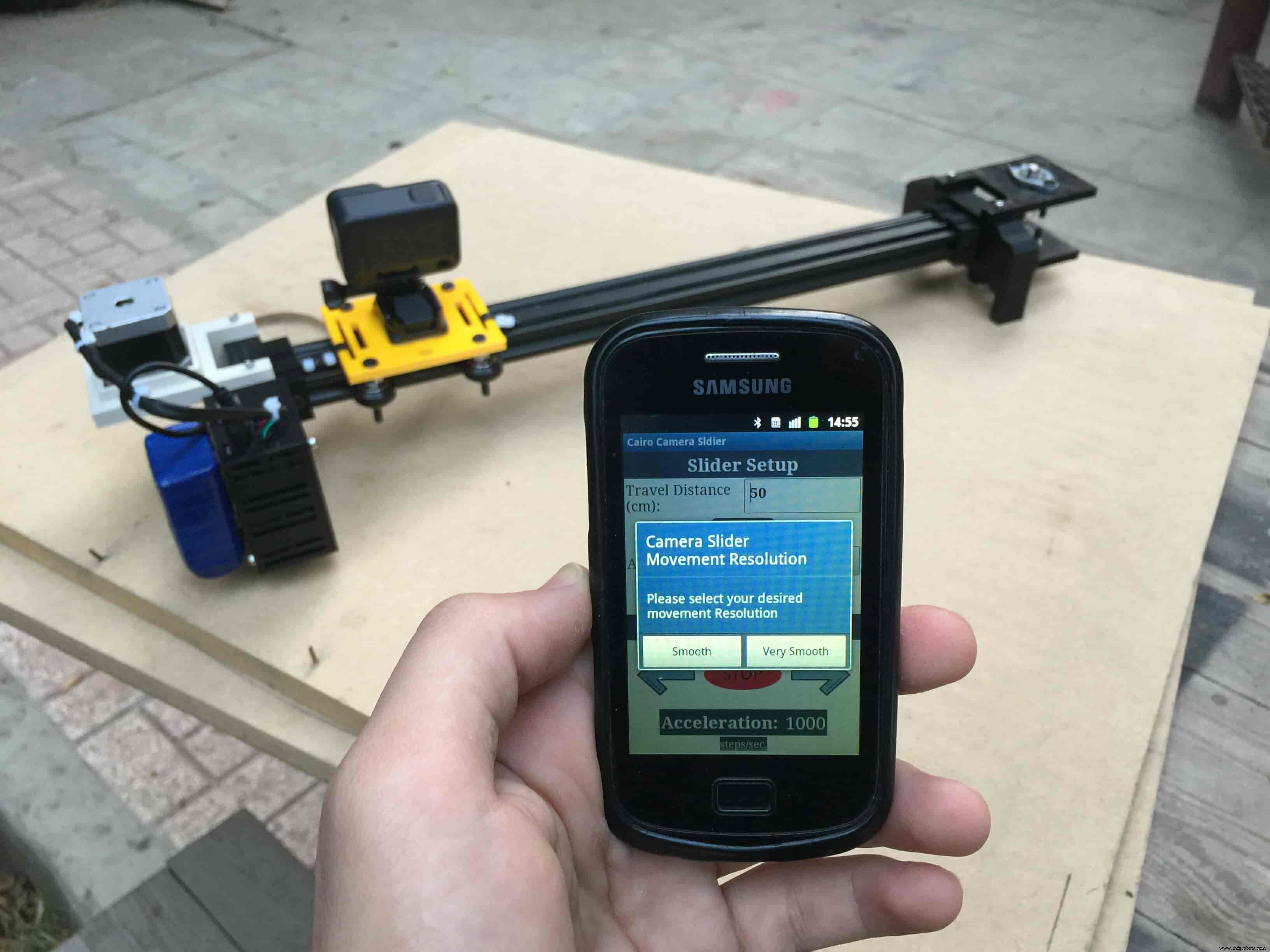
- 1/4 --> Smooth.
- 1/16 --> Very Smooth.

//**************************************************************microstep resolution Part**************************************************
if (incomingData ==18) {
 microStepResolution =4; //50cm rail length @1/4 microstep resolution.
 startupSetupFlag++;

} else if (incomingData ==19) {
 microStepResolution =16; //50cm rail length @1/16 microstep resolution.
 startupSetupFlag++;
}
It sets the camera slider homing if it’s left or right side homing. the homing position, once you click on right or left side homing a specific piece of data will get sent from the mobile app to the Arduino board according to the homing position that you have chosen.

void setup() {
 pinMode(stepPin, OUTPUT);
 pinMode(dirPin, OUTPUT);
 Serial.begin(9600);

 stepper.setMaxSpeed(10.00); //The fastest motor speed that can be reliably supported is about 4000 steps per second at a clock frequency of 16 MHz on Arduino such as Uno
 stepper.setAcceleration(500.00); //1600 (40%) (Medium Acceleration rate)

 while (startupSetupFlag <3) {
 if (Serial.available()> 1) {
 unsigned int dataOne =Serial.read();
 unsigned int dataOne1 =Serial.read();
 unsigned int incomingData =(dataOne1 * 256) + dataOne;

 //**************************************************************Motor Homing Part**************************************************
 if (incomingData ==16) { //left end homing position.
 stepper.setCurrentPosition(steps);
 homingPositionFlag =false;
 startupSetupFlag++;
 }
 else if (incomingData ==17) { //right end homing position.
 stepper.setCurrentPosition(-(steps));
 homingPositionFlag =true;
 startupSetupFlag++;
 }
now it sets how many steps should the stepper motor moves without hitting the camera carriage with the camera slider right or left legs. it reads and saves the rail length according to the value that the user enters in the mobile app. So, depending on the micro-step resolution that the user selected before, and the rail length I can calculate the number of steps that the motor should rotate to reach the limits of the slider rail without hitting the right or left legs.

if (incomingData>=1301 &&incomingData <=2300) {
 railLength =incomingData - 1300; //from raw data to cm.
 if (microStepResolution ==4) {
 steps =((6100L * railLength) / 50L);
 startupSetupFlag++;
 }
 else if (microStepResolution ==16) {
 steps =((25000L * railLength) / 50L);
 startupSetupFlag++;
 }
 }
 }
 //Serial.println(startupSetupFlag);
 }
inside the loop function, it reads the mobile app incoming data and according to these data it takes different actions, like moving the stepper motor clockwise, moving anti-clockwise, stop and return back to the starting point, and changing the traveling speed, so on…
void loop() {

 if (Serial.available()> 1) {

 unsigned int dataOne =Serial.read();
 unsigned int dataOne1 =Serial.read();
 unsigned int incomingData =(dataOne1 * 256) + dataOne;
 //Serial.print("raw data:");
 //Serial.println(incomingData);

 //**************************************************************Motor Control Part**************************************************
 if (incomingData ==1 &&stepper.isRunning() ==false &&stepper.currentPosition() !=6050 &&homingPositionFlag ==true) {
 if (delayedStart ==true) { //use millis to delay 15 seconds.
 delay(15000); //wait 15 seconds.
 }
 stepper.setCurrentPosition(0);
 stepper.moveTo(steps); //from end to end (@ 1/4 step).
 homingPositionFlag =false;

 /*Serial.print("rail length:");
 Serial.print(railLength);
 Serial.print(" number of steps:");
 Serial.print(steps);
 Serial.print(" Homing position:");
 Serial.print(stepper.currentPosition());
 Serial.print(" microstep resolution:");
 Serial.println(microStepResolution);*/
 }

 else if (incomingData ==2 &&stepper.isRunning() ==false &&stepper.currentPosition() !=-6050 &&homingPositionFlag ==false) {
 if (delayedStart ==true) { //use millis to delay 15 seconds.
 delay(15000); //wait 15 seconds.
 }
 stepper.setCurrentPosition(0);
 stepper.moveTo(-(steps)); //from end to end (@ 1/4 step).
 homingPositionFlag =true;

 /*Serial.print("rail length:");
 Serial.print(railLength);
 Serial.print(" number of steps:");
 Serial.print(steps);
 Serial.print(" Homing position:");
 Serial.print(stepper.currentPosition());
 Serial.print(" microstep resolution:");
 Serial.println(microStepResolution);*/
 }

 else if (incomingData ==3 &&stepper.isRunning() ==true) {
 homing();
 }

 //**************************************************************Set Max. Speed Part**************************************************
 else if (incomingData>=5001 &&incomingData <=9000) {
 sliderSpeed =incomingData - 5000;
 stepper.setMaxSpeed(sliderSpeed);
 }

 //**************************************************************Set Delayed Start Part**************************************************
 else if (incomingData ==7) { //delayed start (15 seconds) is checked "true"
 delayedStart =true;
 }
 else if (incomingData ==8) { //delayed start (15 seconds) is not checked "false"
 delayedStart =false;
 }

 //**************************************************************Set movement distance Part**************************************************
 else if (incomingData>=201 &&incomingData <=1200) { //convertin from rail length into number of steps. (upto 10 meters)
 movementDistance =incomingData - 200; //from raw data to cm.
 if (microStepResolution ==4) {
 steps =((6100L * movementDistance) / 50L);
 }
 else if (microStepResolution ==16) {
 steps =((25000L * movementDistance) / 50L);
 }
 /*Serial.print("rail length:");
 Serial.print(movementDistance);
 Serial.print(" number of steps:");
 Serial.println(steps);*/
 }

 //**************************************************************Set Acceleration Part**************************************************
 else if (incomingData ==11 &&stepper.isRunning() ==false) { //HIGH
 stepper.setAcceleration(3000);
 }

 else if (incomingData ==12 &&stepper.isRunning() ==false) { //Medium
 stepper.setAcceleration(1000);
 }

 else if (incomingData ==13 &&stepper.isRunning() ==false) { //Low
 stepper.setAcceleration(500);
 }

 else if (incomingData ==14 &&stepper.isRunning() ==false) { //Very High
 stepper.setAcceleration(4000);
 }

 else if (incomingData ==15 &&stepper.isRunning() ==false) { //Very Low
 stepper.setAcceleration(10);
 }
 }
 stepper.run();
}

void homing() {
 if (stepper.currentPosition()> 0) {
 homingPositionFlag =true;
 } else {
 homingPositionFlag =false;
 }
 stepper.moveTo(0);
}
Cairo Camera Slider User Guide &troubleshooting
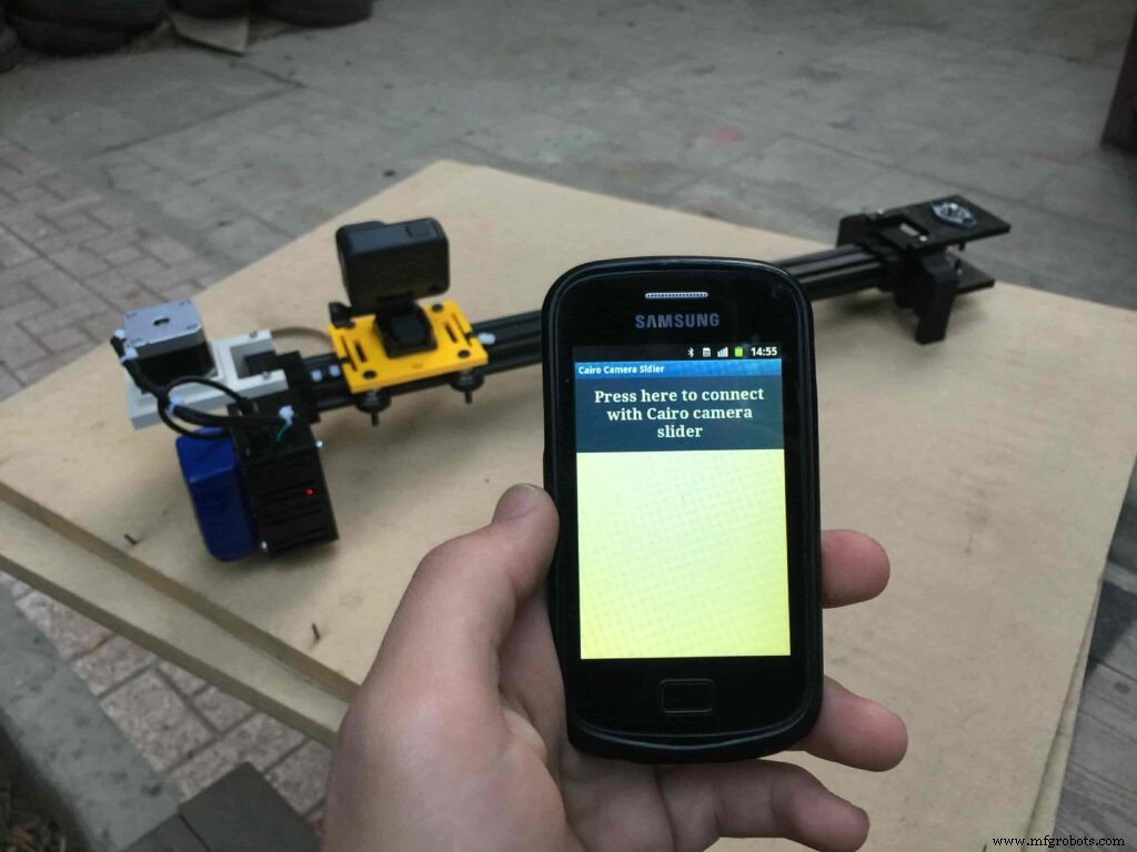
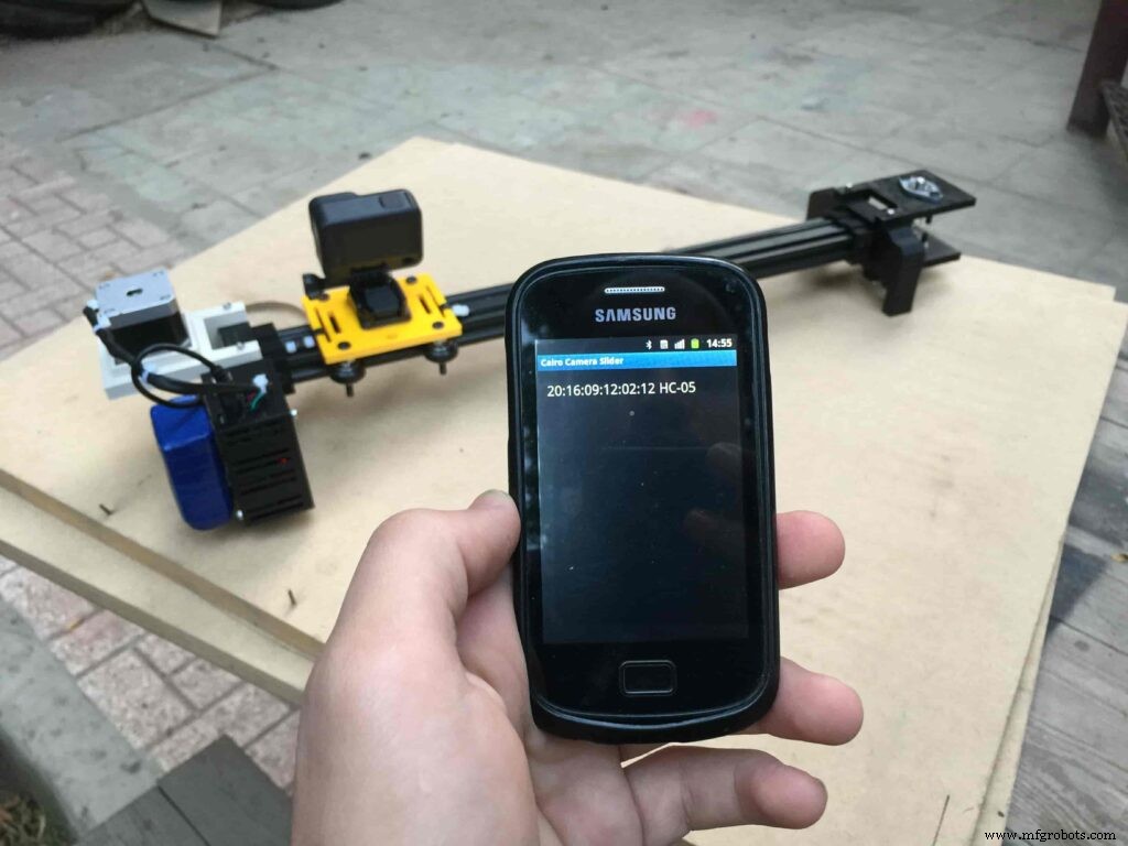
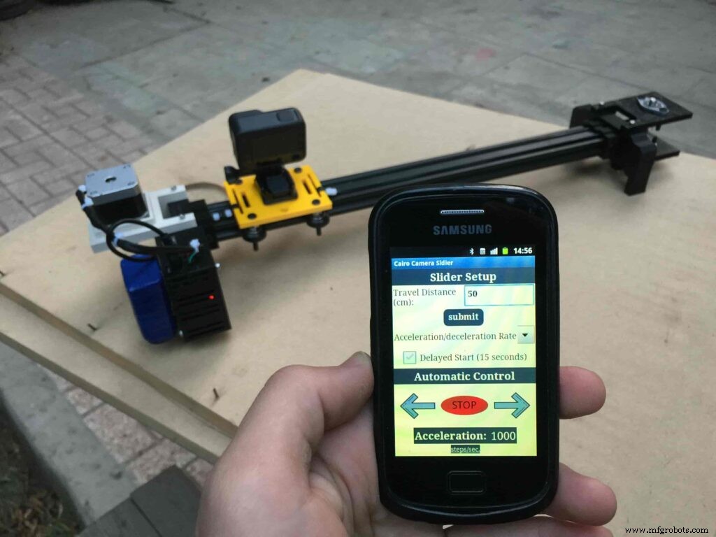
After connecting the 12V power source to the Arduino UNO board that distributes power to the Cairo camera slider Arduino shield as well, turn on the Bluetooth on your mobile, search for new devices, pair with the HC-05 device, and open the mobile app then press on the “Press here to connect with Cairo camera slider” button. It will show up the menu of the paired Bluetooth devices, select the HC-05 Bluetooth device.
After connecting successfully with the Control board, the mobile app will ask you some questions to set up some parameters. First question will ask you about the micro-step resolution of the stepper motor driver if it’s smooth(1/4 micro-step), or very smooth(1/16 micro-step). select the mode According to the micro-stepping resolution mode that you set the A4988 driver at. If you selected a wrong mode The Cairo camera slider will not work correctly.
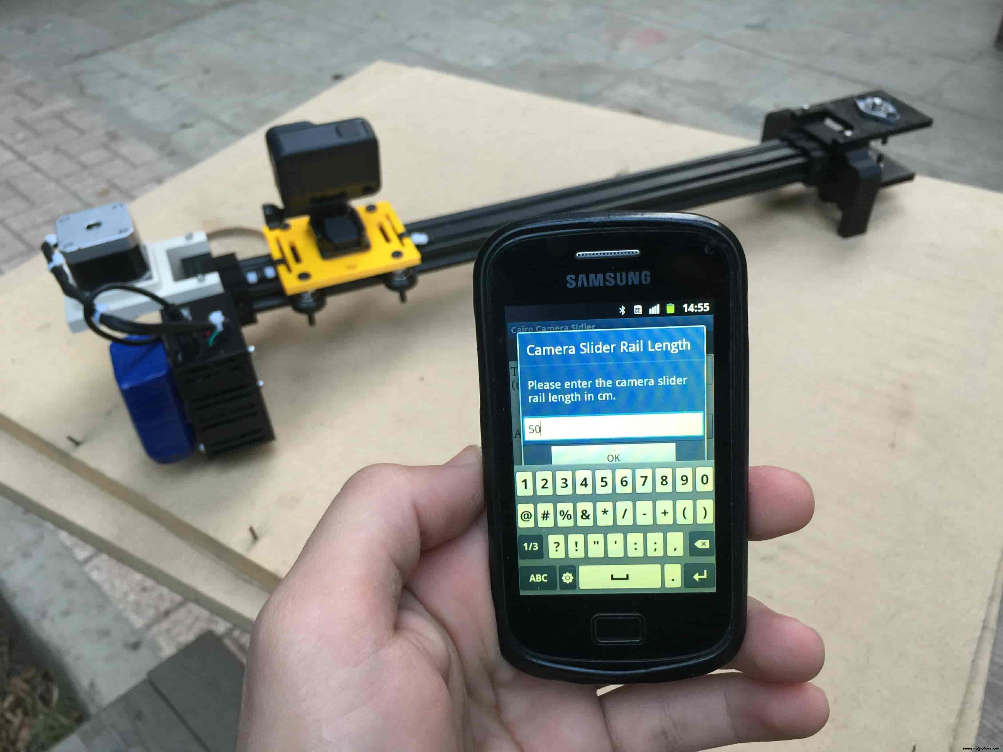
Then, it will ask you about the aluminum rail length that you are using in your camera slider. Enter the distance in CM. in my case I’m using a 50cm rail length.
Lastly, it will ask you about the camera carriage homing position, It’s very important to place the camera carriage on one of the two rail ends, the right end or the left end. In my case, the camera carriage is on the left end. So, I selected the left end homing.
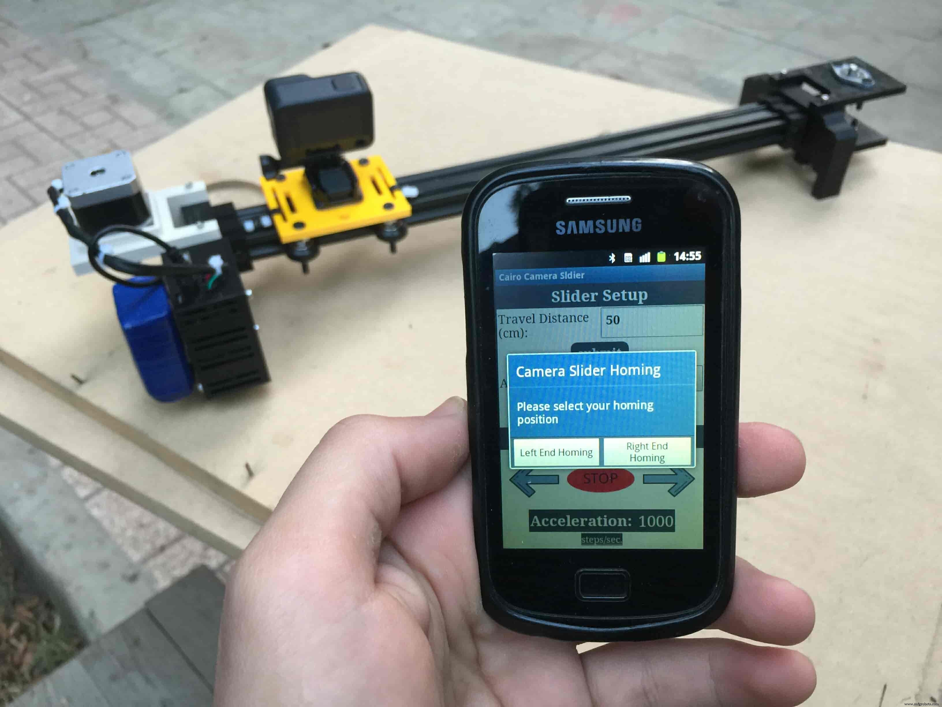
If you started the Cairo camera slider and the camera carriage is on the middle of the rail or not on one of the two rail ends it will cause the carriage to hit the limits when it moves.
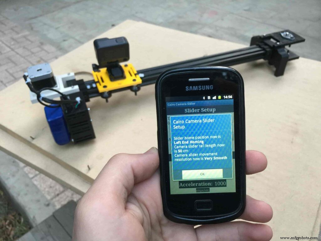
After you finish the set-up process, It will show you the parameters that you have set. And once you click OK, you will be ready to play around with your lovely Cairo camera slider.
Cairo Camera Slider In-Action
Code
- Cairo Camera Slider Final Code
Cairo Camera Slider Final CodeArduino
/* TODO::Update the arduino program to Make the user able to choose the motor driver micro stepping mode. find and equation that helps to automatically adjust the the "steps" variable value. TODO::update the mobile app to ask the user on the beginning only about the [homing position(done), microstepping mode]. TODO::Update the arduino program to make the code only iterates around the "homing position" &"microstepping mode" only once on the void setup() function. DATA::left arrow button sends --> 1. DATA::right arrow button sends --> 2. DATA::stop button sends --> 3. DATA::rail length (1cm - 1000cm) --> (201 - 1200). DATA::motor acceleration spinner Very High --> 14. DATA::motor acceleration spinner High --> 11 DATA::motor acceleration spinner Medium --> 12 DATA::motor acceleration spinner Low --> 13 DATA::motor acceleration spinner Very Low --> 15 DATA::motor speed slider (1 step/sec. - 4000 step/sec.) --> (5001 - 9000). DATA::delay start checkbox is true --> 7. DATA::delay start checkbox is false --> 8. DATA::left end homing --> 16. DATA::right end homing --> 17. DATA::Smooth movement Type --> 18. DATA::Very Smooth movement Type --> 19. 1301 --> 2300*/#include#include #define stepPin 2#define dirPin 3bool homingPositionFlag =false;int startupSetupFlag =0;bool delayedStart =false;int incomingData =0;int movementDistance =50;long steps =0; //50cm rail by default @1/8 microstepping.int microStepResolution =0; //4 or 16long railLength =0;int sliderSpeed =10;AccelStepper stepper(AccelStepper::DRIVER, stepPin, dirPin); //create an object. the pin "2" is the step pin, "3" is the direction pin.void setup() { pinMode(stepPin, OUTPUT); pinMode(dirPin, OUTPUT); Serial.begin(9600); stepper.setMaxSpeed(10.00); //The fastest motor speed that can be reliably supported is about 4000 steps per second at a clock frequency of 16 MHz on Arduino such as Uno stepper.setAcceleration(500.00); //1600 (40%) (Medium Acceleration rate) while (startupSetupFlag <3) { if (Serial.available()> 1) { unsigned int dataOne =Serial.read(); unsigned int dataOne1 =Serial.read(); unsigned int incomingData =(dataOne1 * 256) + dataOne; //**************************************************************Motor Homing Part************************************************** if (incomingData ==16) { //left end homing position. stepper.setCurrentPosition(steps); homingPositionFlag =false; startupSetupFlag++; } else if (incomingData ==17) { //right end homing position. stepper.setCurrentPosition(-(steps)); homingPositionFlag =true; startupSetupFlag++; } //**************************************************************microstep resolution Part************************************************** if (incomingData ==18) { microStepResolution =4; //50cm rail length @1/4 microstep resolution. startupSetupFlag++; } else if (incomingData ==19) { microStepResolution =16; //50cm rail length @1/16 microstep resolution. startupSetupFlag++; } if (incomingData>=1301 &&incomingData <=2300) { railLength =incomingData - 1300; //from raw data to cm. if (microStepResolution ==4) { steps =((6100L * railLength) / 50L); startupSetupFlag++; } else if (microStepResolution ==16) { steps =((25000L * railLength) / 50L); startupSetupFlag++; } } } //Serial.println(startupSetupFlag); } /* * *********** *********** **********For Debugging Purposes* *********** *********** ********** Serial.print("rail length:"); Serial.print(railLength); Serial.print(" number of steps:"); Serial.print(steps); Serial.print(" Homing position:"); Serial.print(stepper.currentPosition()); Serial.print(" microstep resolution:"); Serial.println(microStepResolution);*/}void loop() { if (Serial.available()> 1) { unsigned int dataOne =Serial.read(); unsigned int dataOne1 =Serial.read(); unsigned int incomingData =(dataOne1 * 256) + dataOne; //Serial.print("raw data:"); //Serial.println(incomingData); //**************************************************************Motor Control Part************************************************** if (incomingData ==1 &&stepper.isRunning() ==false &&stepper.currentPosition() !=6050 &&homingPositionFlag ==true) { if (delayedStart ==true) { //use millis to delay 15 seconds. delay(15000); //wait 15 seconds. } stepper.setCurrentPosition(0); stepper.moveTo(steps); //from end to end (@ 1/4 step). homingPositionFlag =false; /*Serial.print("rail length:"); Serial.print(railLength); Serial.print(" number of steps:"); Serial.print(steps); Serial.print(" Homing position:"); Serial.print(stepper.currentPosition()); Serial.print(" microstep resolution:"); Serial.println(microStepResolution);*/ } else if (incomingData ==2 &&stepper.isRunning() ==false &&stepper.currentPosition() !=-6050 &&homingPositionFlag ==false) { if (delayedStart ==true) { //use millis to delay 15 seconds. delay(15000); //wait 15 seconds. } stepper.setCurrentPosition(0); stepper.moveTo(-(steps)); //from end to end (@ 1/4 step). homingPositionFlag =true; /*Serial.print("rail length:"); Serial.print(railLength); Serial.print(" number of steps:"); Serial.print(steps); Serial.print(" Homing position:"); Serial.print(stepper.currentPosition()); Serial.print(" microstep resolution:"); Serial.println(microStepResolution);*/ } else if (incomingData ==3 &&stepper.isRunning() ==true) { homing(); } //**************************************************************Set Max. Speed Part************************************************** else if (incomingData>=5001 &&incomingData <=9000) { sliderSpeed =incomingData - 5000; stepper.setMaxSpeed(sliderSpeed); } //**************************************************************Set Delayed Start Part************************************************** else if (incomingData ==7) { //delayed start (15 seconds) is checked "true" delayedStart =true; } else if (incomingData ==8) { //delayed start (15 seconds) is not checked "false" delayedStart =false; } //**************************************************************Set movement distance Part************************************************** else if (incomingData>=201 &&incomingData <=1200) { //convertin from rail length into number of steps. (upto 10 meters) movementDistance =incomingData - 200; //from raw data to cm. if (microStepResolution ==4) { steps =((6100L * movementDistance) / 50L); } else if (microStepResolution ==16) { steps =((25000L * movementDistance) / 50L); } /*Serial.print("rail length:"); Serial.print(movementDistance); Serial.print(" number of steps:"); Serial.println(steps);*/ } //**************************************************************Set Acceleration Part************************************************** else if (incomingData ==11 &&stepper.isRunning() ==false) { //HIGH stepper.setAcceleration(3000); } else if (incomingData ==12 &&stepper.isRunning() ==false) { //Medium stepper.setAcceleration(1000); } else if (incomingData ==13 &&stepper.isRunning() ==false) { //Low stepper.setAcceleration(500); } else if (incomingData ==14 &&stepper.isRunning() ==false) { //Very High stepper.setAcceleration(4000); } else if (incomingData ==15 &&stepper.isRunning() ==false) { //Very Low stepper.setAcceleration(10); } } stepper.run();}void homing() { if (stepper.currentPosition()> 0) { homingPositionFlag =true; } else { homingPositionFlag =false; } stepper.moveTo(0);}
Custom parts and enclosures
Cairo Camera Slider STLs
CAD file on thingiverse.comSchematics

Производственный процесс